Connecting
The robot needs three connections to run. They are on the back of the base.
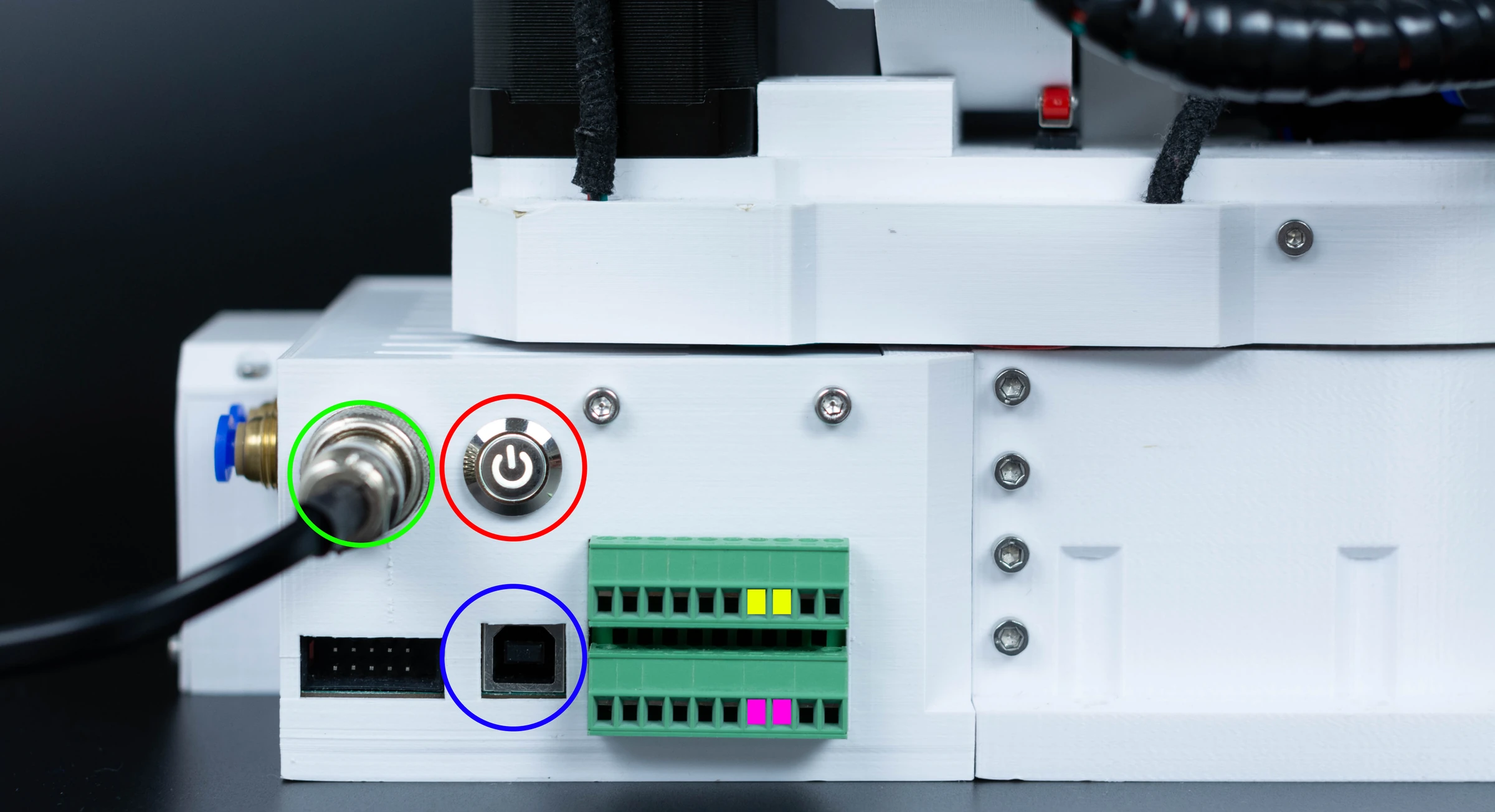
| Connection | Connector | Notes |
|---|---|---|
| 24 V power | GX16 2-pin | From the 24 V 5 A supply (The power supply). Mind the polarity when you wire your own cable: the board has no reverse-polarity protection |
| USB | USB type B | To the PC. USB does not power the board |
| E-stop | Two screw terminals | A normally closed contact between them. Open means stop |
Plug the power supply into the mains through a switch within your reach, a switched socket strip for example: it is the stop that still works when the PC software has frozen (Emergency stop).
The power supply
The robot needs 24 V DC at 5 A or more, into its GX16 socket. There are two good ways to get it: a closed supply with a mains cable, which needs no mains wiring, or the DIN-rail supply in the BOM, whose mains side you wire yourself.
Mains voltage kills
The mains side of a power supply carries 230 V or 120 V. Never open, wire or touch it while the plug is in the socket. If you are not sure how to wire it, use a closed supply (A), or have a qualified electrician wire the DIN-rail supply (B).
A. A closed supply with a mains cable
The simplest safe choice: a closed 24 V supply of at least 5 A (120 W), a desktop power brick with a moulded mains cable and plug, approved for your country. There is nothing to wire on its mains side. On its 24 V side:
- Its output plug will not fit the robot. Fit a GX16 2-pin plug to its output cable, or make a short adapter cable with the brick's mating socket on one end and a GX16 plug on the other.
- Find + and − on the output with a multimeter, and wire + to the GX16 pin that the robot's socket takes to the board's +. The board has no reverse-polarity protection.
B. The Mean Well EDR-120-24 from the BOM
A 120 W DIN-rail supply with screw terminals and no mains cable. From Mean Well's EDR-120 datasheet:
| Input | 90 to 264 V AC, 47 to 63 Hz |
| Input terminals | FG (earth), AC/L (live), AC/N (neutral) |
| Output terminals | Two −V and two +V, 24 V, 5 A: the robot's cable to one +V and one −V |
| Output adjustment | +V ADJ, 24 to 28 V. The board takes 24 V at most: leave it at 24 V |
| Room around it | 40 mm above, 20 mm below, 5 mm at the sides, at full load |
You need:
- A mains cable with three wires, earth included, and a moulded plug. Never a two-wire cable.
- Wire ferrules crimped on the stranded ends, so that no strand escapes the terminal.
- Strain relief: the cable clamped where it enters, so that a pull on the cable never reaches the terminals.
- The earth wire always connected, to FG.
- An enclosure: the supply on a DIN rail (TS35) in a closed box, or at least a cover over its terminals, so that no live screw can be touched. A plastic box is simplest; a metal one must be earthed as well.
| Terminal | Europe and the UK | USA and Canada |
|---|---|---|
| AC/L, live | brown | black |
| AC/N, neutral | blue | white |
| FG, earth | green-yellow | green |
Other countries can use other colours: check, and do not guess.
Check before the first power-on, in this order:
- The plug is out of the socket.
- Each wire is in the right terminal, by the table above, with no loose strands; a gentle pull on each wire moves nothing.
- With a multimeter: the plug's earth pin to the FG terminal reads close to 0 Ω.
- The box or the terminal cover is closed, and the cable is clamped.
- The robot is not connected yet. Plug in: the supply's DC OK lamp lights. At the GX16 plug, measure 24 V, with + and − on the pins the robot's socket expects.
- Unplug, connect the robot, plug in through the switch within reach.
If you are not sure about any step, have a qualified electrician wire the supply.
The E-stop
The E-stop must be a normally closed contact: pressing it, unplugging it or cutting its wire opens the circuit, and all of these stop the robot, which is what you want. A normally open button does not work. The control board has two E-stop connectors on the same input, so a second button can be wired in series.
The kit's button comes with a printed housing and a PG7 cable gland. Emergency stop says what happens when it is pressed, and the Control Board Manual has the wiring diagram.
The gripper
An electric gripper (SSG-48, MSG) plugs into the M8 connector at the forearm, which carries 24 V and CAN: Electric grippers. Pneumatic tubes from the valve go to the two push-in fittings at the base: Pneumatics.
Inputs and outputs
The two inputs, two outputs and their supply terminals are on the side of the control board, reachable through the base: Inputs and outputs.
Nothing else on the programming port
The 2×5-pin programming header next to the USB port is for the ST-Link programming adapter only. An ST-Link connected with plain jumper wires without the adapter has destroyed boards. See Firmware.
Comments
Found a mistake on this page? Edit it on GitHub · Report it · Get help · This page as Markdown · llms.txt · The whole manual as PDF