Firmware and first run
1. The test firmware
A control board from the shop ships with the test firmware. Use it, with the base open and the motors not yet
driving the arm, to check every driver, every switch and sensor, and the I/O from a serial terminal: on the bench
before the arm is assembled, as in Electronics and wiring.
At power-on it prints a report on
each driver (joint N Connection is: GOOD or BAD) and turns every motor slowly; #LIMIT then shows the
switches and #IO the E-stop, the inputs and the supply voltage. The test firmware
has the commands and what good output looks like.
Danger
The test firmware turns all six motors slowly from the moment it boots until the power is switched off; no command stops them. On an assembled arm joints 1 to 5 reach their blockers within about a minute and keep pushing. Use it with the motors free to turn, never on an assembled robot.
Check
Six Connection is: GOOD lines in the report; #LIMIT names each switch while you press it; #IO follows
the E-stop and the inputs and shows the supply near 24000 mV. If not:
Control board troubleshooting.
2. Upload the main firmware
The main firmware is in the repository under PAROL6 control board main software; it is a PlatformIO project
for VS Code. Install VS Code and the PlatformIO extension, open the folder, and upload with an ST-Link through the
programming adapter, with the 24 V supply disconnected: Firmware has the procedure and
the warnings.
Check
PlatformIO ends the upload with SUCCESS. If not: Control board troubleshooting.
3. First power-on
Unplug the programming adapter, plug in the supply, hold the forearm and press the button. Six clicks, and the arm holds. Start the commander software, connect, and open the joint jog menu.
Check
Six clicks, the fan runs, the arm holds itself, and the commander shows the robot's data. If not: First power-on: if nothing happens.
4. A joint turns the wrong way
Jog each joint briefly. The joint must turn as in the figure, which shows each joint's positive direction
(Joint limits and directions). Before homing, the commander checks jogs
against the joint limits with a position count that starts at 0, so some directions are refused with
Error: Robot jog -> Position out of range:
- Joint 2: press its right arrow (negative). It must turn opposite to the figure; its left arrow does nothing until the robot is homed.
- Joints 1, 3, 4, 5 and 6: press the left arrow (positive). It must turn as in the figure.
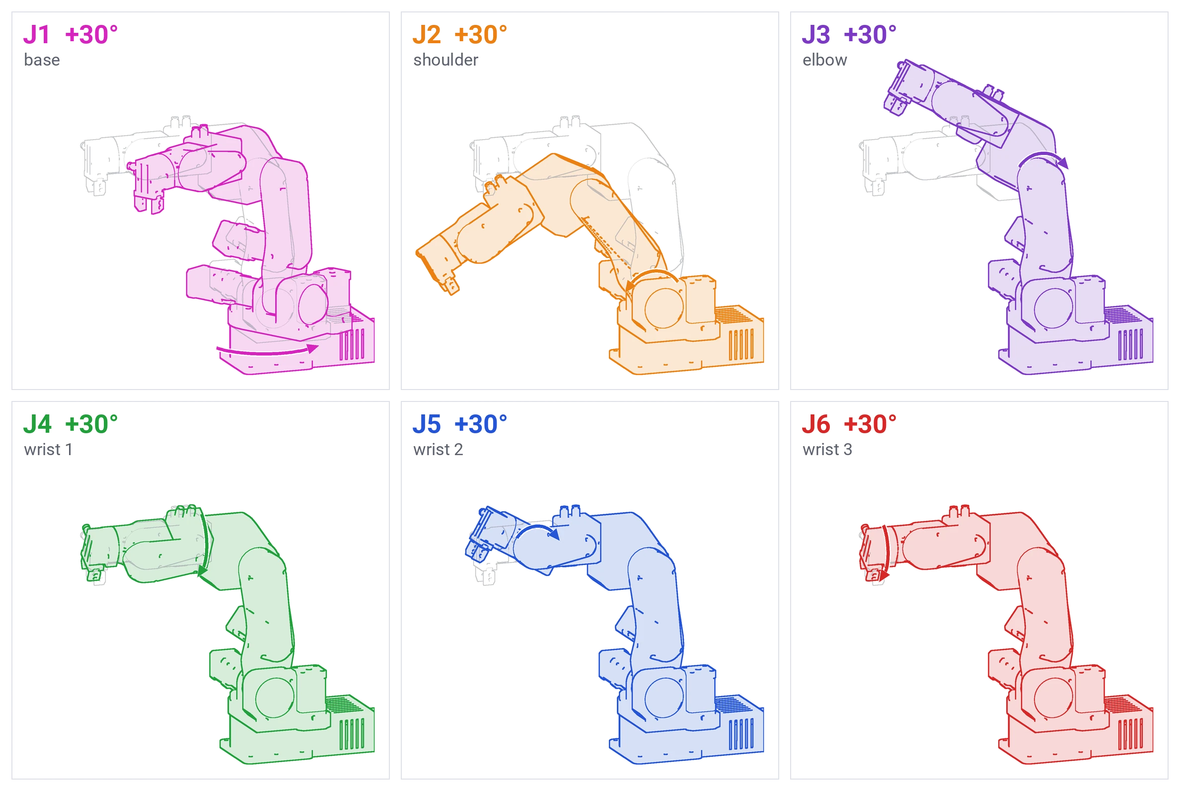
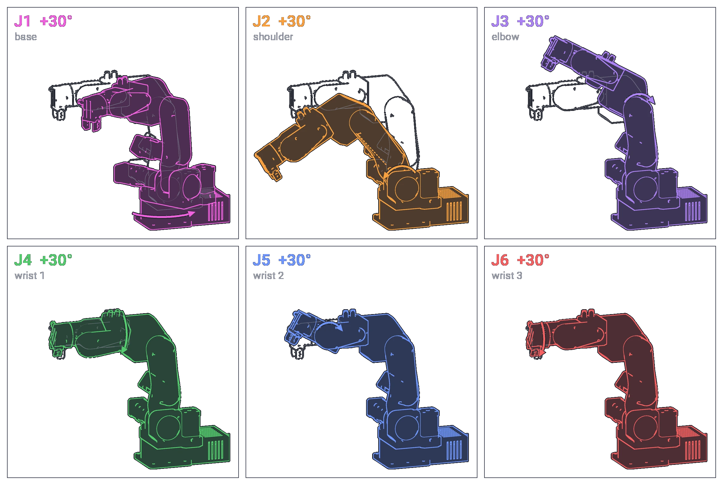
A joint that turns the other way is the most common first-run problem, and it is fixed in the firmware, not by rewiring:
Upload again and check again. Swapping one motor phase's wires has the same effect, if you prefer to open the base.
Check
The left arrows of joints 1 and 3 to 6 turn them as in the figure, and joint 2's right arrow turns it the opposite way.
5. Home
With every direction right, set joint 6 and check the tool's homing offset as in Before you press Home, then press Home and stay at the E-stop. The sequence is on Homing; if a joint grinds at a stop, press the E-stop and see Homing failures.
Check
Homing finishes, the simulator matches the robot, and the pin passes through the witness marks of each joint, which line up in the after-homing pose (Witness marks).
The commander's terminal output
While it runs, the commander prints the robot's data to its terminal: the positions, the homed and I/O bytes,
the errors, the gripper data, and Time between 2 commands in ms, which should be near 0.010 (the number is in
seconds, despite the label: 0.010 is 10 ms). Watch it for a few minutes while jogging: if it is often much higher,
the PC is too slow (Communication).
Comments
Found a mistake on this page? Edit it on GitHub · Report it · Get help · This page as Markdown · llms.txt · The whole manual as PDF