Reference frames
A frame is a coordinate system: an origin and three axes, X, Y and Z, at right angles. A position is three numbers in a frame; the same point has different numbers in different frames. PAROL6's software uses two frames you choose between, the world frame and the tool frame, and several it keeps to itself, the flange frame among them.
The right-hand rule
All frames are right-handed: with the right hand's thumb along X and the index finger along Y, the middle finger points along Z. For rotations, the thumb along the axis, the fingers curl in the positive direction. Every orientation angle in the software follows this rule.
The frames on the robot
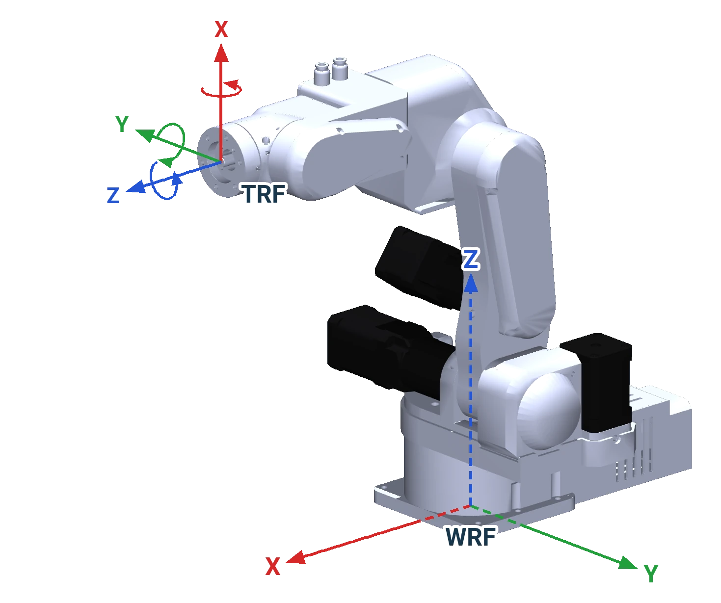
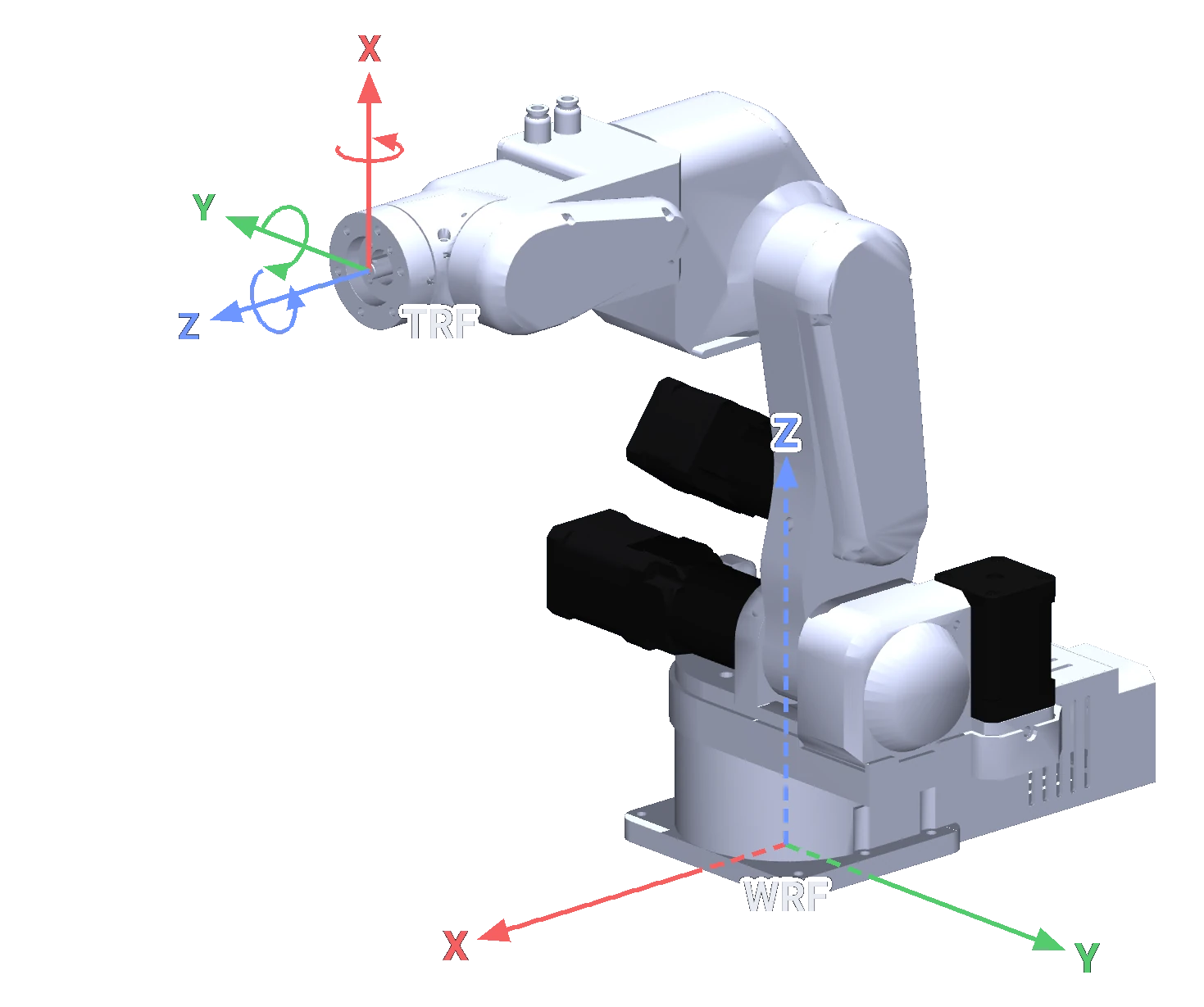
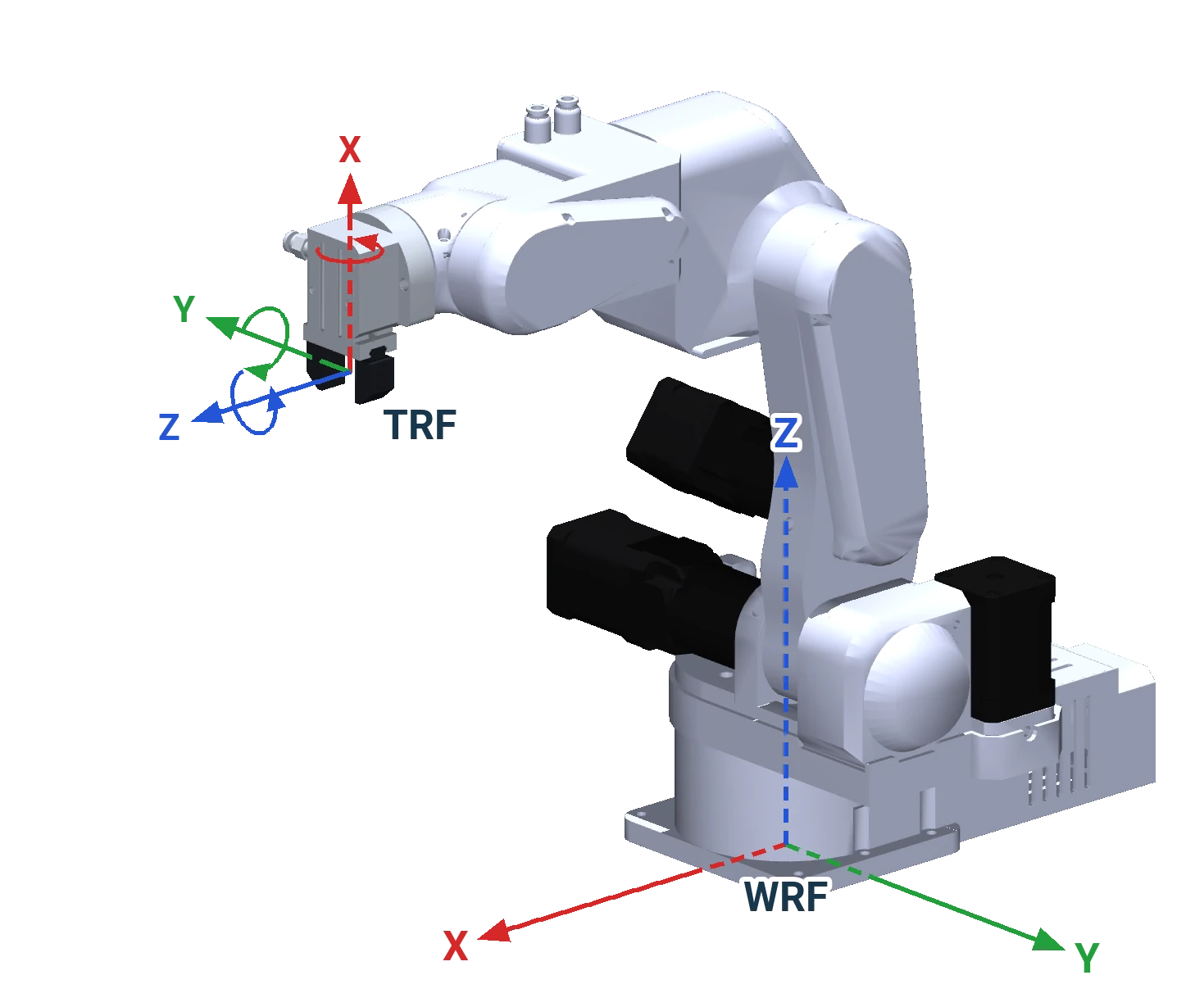
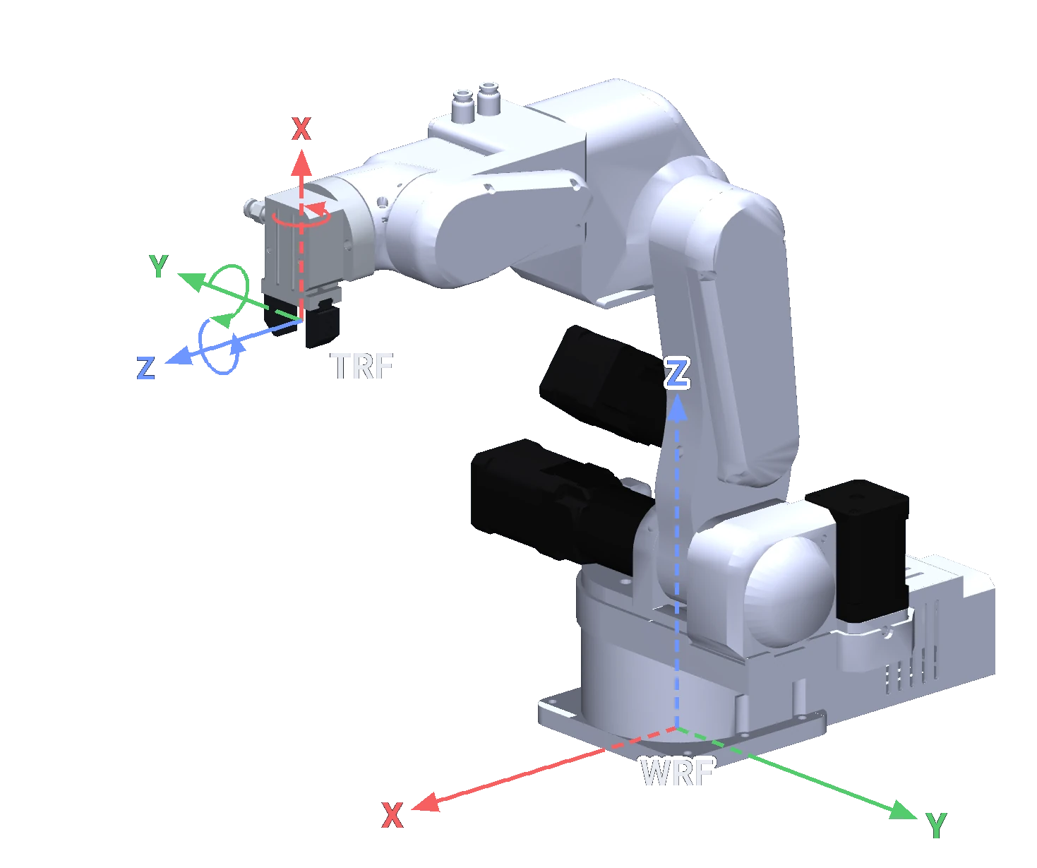
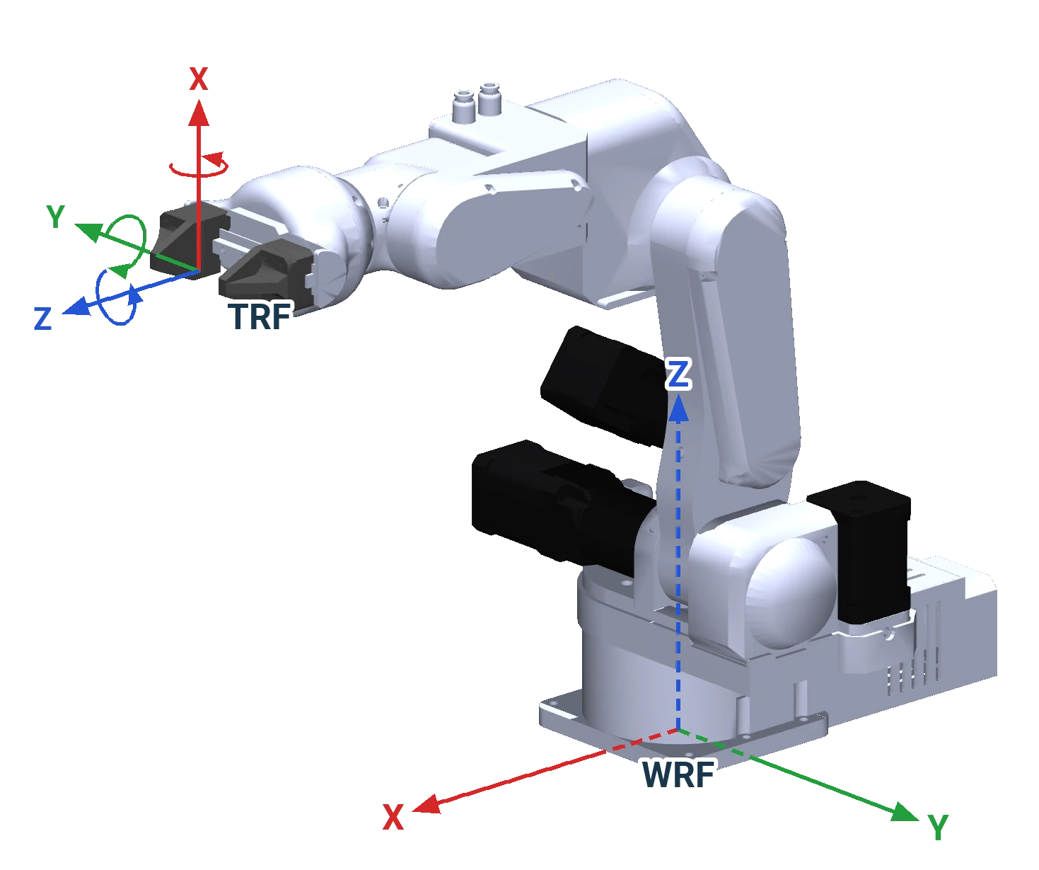
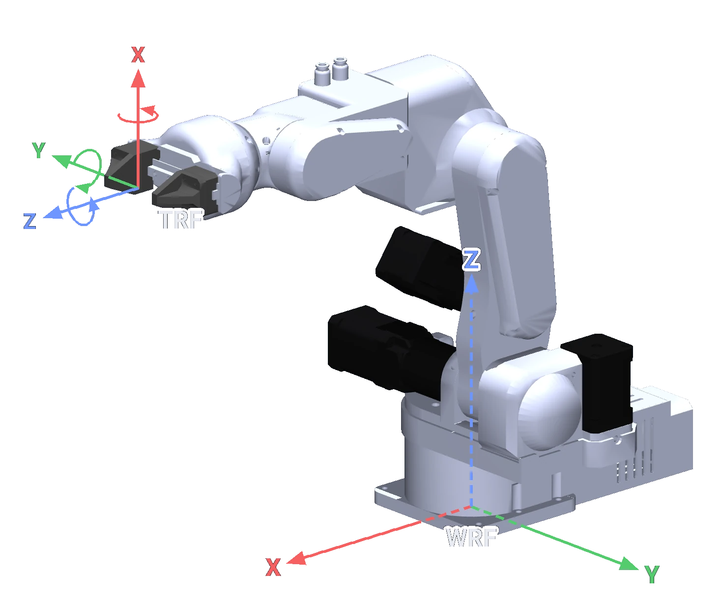
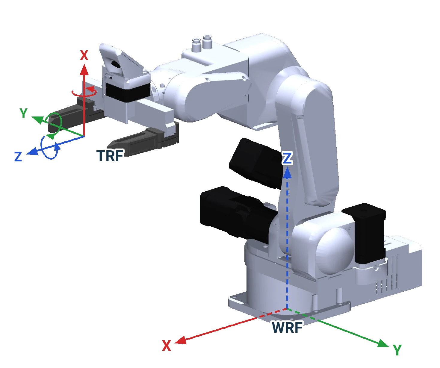
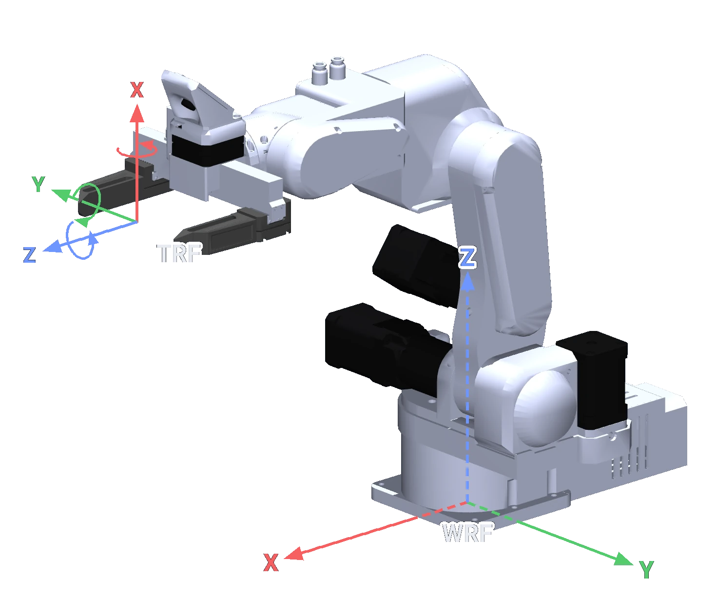
The pictures show the frames on the robot's model, in the commander software's convention, which these pages use: X red, Y green, Z blue. The arcs at the tool frame are the positive rotations RX, RY and RZ. An axis is dashed where it runs inside the robot. The directions in the table are those of the standby pose.
In the Python API, the tool frame's Y and Z point the other way
In the Python API (version 0.9.1) the flange and tool frames are these frames turned 180° about X: X is the
same, Y and Z point the other way, so the API's Z points back into the wrist. A TRF move or jog, or a TCP
offset, "out of the tool" is negative z there: move_l([0, 0, -20, 0, 0, 0], frame="TRF", rel=True) moves the
tool 20 mm out along the joint 6 axis, and set_tcp_offset(0, 0, -120) puts the TCP 120 mm in front of the
flange. The code examples on these pages are written for the API as it is
(known issue KI-11).
| Frame | Origin | X | Y | Z |
|---|---|---|---|---|
| WRF | On the joint 1 axis, at the base's mounting surface | Forward: the way the arm points in the standby pose, away from the electronics case | To the left, seen from behind the robot: the way the arm points after homing | Up, along the joint 1 axis |
| Flange frame | On the joint 6 axis, at the flange face | Up; it turns with joint 6 | To the robot's right | Out of the flange, along the joint 6 axis |
| TRF | At the tool centre point (TCP) | As the flange frame | As the flange frame | As the flange frame: out of the tool, along the joint 6 axis |
WRF, the world reference frame
Fixed to the robot's base, as in the table: X the way the arm points in the standby pose, Y the way it points
after homing, Z up. Everything that does not move with the arm is described in it: the table, the parts, the
positions a program teaches. MoveCart in RBTscript and move_l in the API take WRF poses by default. The
commander software and the Python API agree on it.
TRF, the tool reference frame
Fixed to the tool: the origin at the tool centre point, the axes those of the flange frame. It moves with the
arm. Z points out of the tool along the joint 6 axis, the way the SSG-48's and the MSG's jaws point; the pneumatic
gripper's fingers hang beside the axis and point along −X. A move in the TRF is relative to where the tool is
now: "100 mm out along the tool" is MoveCartRelTRF(0,0,100,0,0,0) in the commander, and
move_l([0, 0, -100, 0, 0, 0], frame="TRF", rel=True) in the Python API, whose Z points the other way (above). It
goes in a different world direction every time, depending on the tool's orientation. Approaching a part along
the gripper's axis, retreating after a grip, and rotating the tool about its own axis are TRF moves. Jog slowly
in the TRF before you run a TRF move written for the other program.
The flange frame
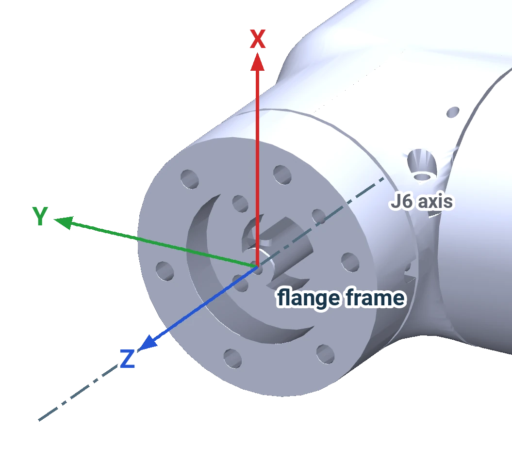
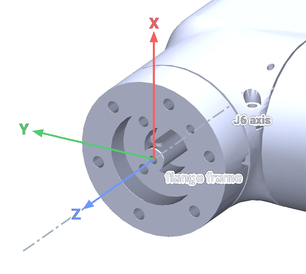
Every tool is measured from the flange frame. Its origin is on the joint 6 axis at the flange face, 50.5 mm from the wrist centre (the point where the axes of joints 4, 5 and 6 meet), and its Z axis points out of the flange along that axis. X and Y turn with joint 6: in the standby pose, with joint 6 at 180°, X points up. The Python API's built-in model puts the origin 37 mm from the wrist centre, 13.5 mm short of the face, measures its tool offsets from there, and has Y and Z the other way (above).
The TCP of each tool
| Tool | select_tool key, variants |
The API's offset, in its own axes: x, y, z | From the wrist centre, along the tool and beside it: API | The same in the model: a6, a7 | Fingers point along; jaws close along |
|---|---|---|---|---|---|
| Bare flange | NONE |
0, 0, 0 mm | 37 mm, 0 | 50.5 mm, 0 | |
| Pneumatic gripper | PNEUMATIC, vertical (the default) |
−55, 0, −27 mm | 64 mm, 55 mm | 62.3 mm, 45.25 mm | −X; Y |
| Pneumatic gripper | PNEUMATIC, horizontal |
0, 0, −82 mm | 119 mm, 0 | not in the model | Z; X |
| SSG-48 | SSG-48, finger, pinch |
0, 0, −105 mm | 142 mm, 0 | 134.3 mm, 0 | Z; Y |
| MSG | MSG, 100mm, 150mm, 200mm |
−29, 0, −109.5 mm | 146.5 mm, 29 mm | 134.3 mm, 28.35 mm | Z; Y |
| Vacuum gripper | VACUUM |
0, 0, −37 mm | 74 mm, 0 | not in the model |
Every tool frame has the flange frame's axes: the Python API's tool definitions are offsets, with no rotation,
and their negative z is out of the tool. A TCP beside the tool axis lies along the flange frame's −X, below the
joint 6 axis in the standby pose. The model's TCP sits between the fingers, near their tips; the API's offsets
come from the earlier model and differ from the model's by up to about 14 mm. The pictures above are drawn at the
model's TCP. set_tcp_offset() and set_tcp_transform() move the TCP for a correction or a tool
of your own (Tools and the TCP).
Jogging in a frame
The commander's Cartesian jog and the API's jog_l take the frame: WRF jogs move the tool along the base's
axes, TRF jogs along the tool's own. Switch to TRF to go straight in or out of a part whatever its angle.
In the TRF column, +Z is out of the tool in the commander and into the wrist in the Python API.
| Jog | In the WRF | In the TRF |
|---|---|---|
| X, Y, Z | The TCP moves along the base's X, Y or Z; the tool keeps its orientation | The TCP moves along the tool's own X, Y or Z, as the tool stands; the tool keeps its orientation |
| RX, RY, RZ | The tool turns about a line through the TCP, parallel to the base's X, Y or Z; the TCP stays where it is. The Python API only: the commander's WRF rotation buttons do nothing | The tool turns about its own X, Y or Z, through the TCP; the TCP stays where it is |
Orientation
A pose gives the tool frame's orientation in the world frame as three angles in degrees. The Python API reads them as intrinsic XYZ rotations, R = Rx · Ry · Rz, of its own tool frame: after homing, with the tool horizontal and pointing away from the base, an API pose ends in 90, 0, 90. Pose and orientation explains the angles.
The frames inside
The kinematic model keeps a frame at every joint, each defined relative to the previous one by the
Denavit-Hartenberg parameters, and the flange frame. The tool frame is the flange frame moved by the tool's
transform; the Python API's tool definitions and set_tcp_transform() set that transform
(Tools and the TCP). The commander's model has the pneumatic gripper's
transform built in.
Comments
Found a mistake on this page? Edit it on GitHub · Report it · Get help · This page as Markdown · llms.txt · The whole manual as PDF