Dimensions and kinematics
Drag to turn the robot, scroll to zoom, move each joint with its slider, choose the gripper on the flange, try a colour for the printed parts (the motors stay black). The model is the robot's URDF; the sliders run over its joint limits.
Dimensions
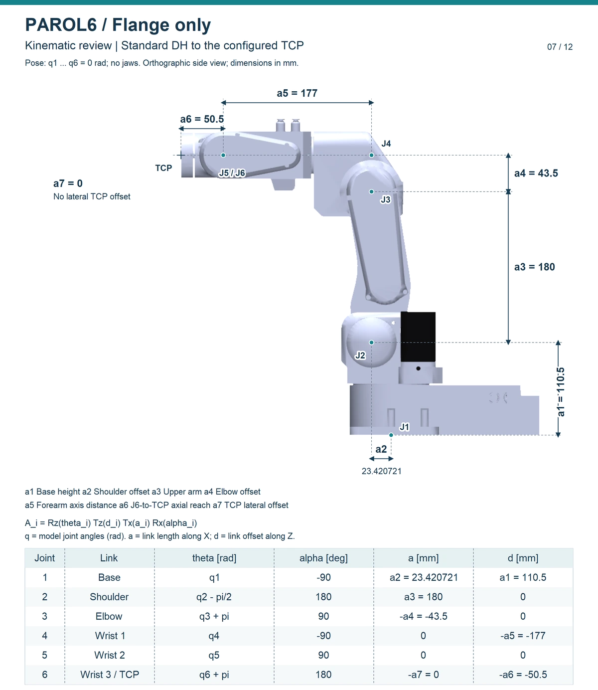
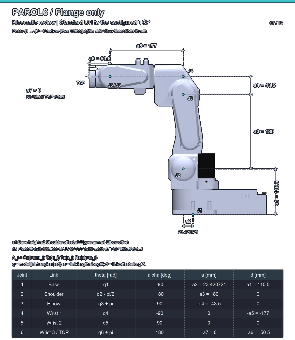
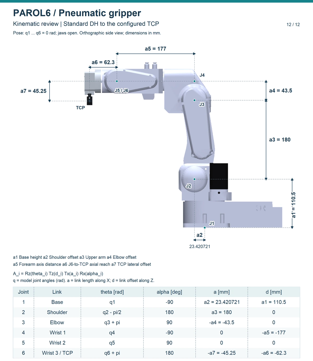
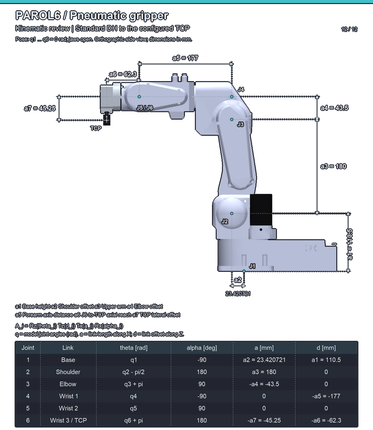
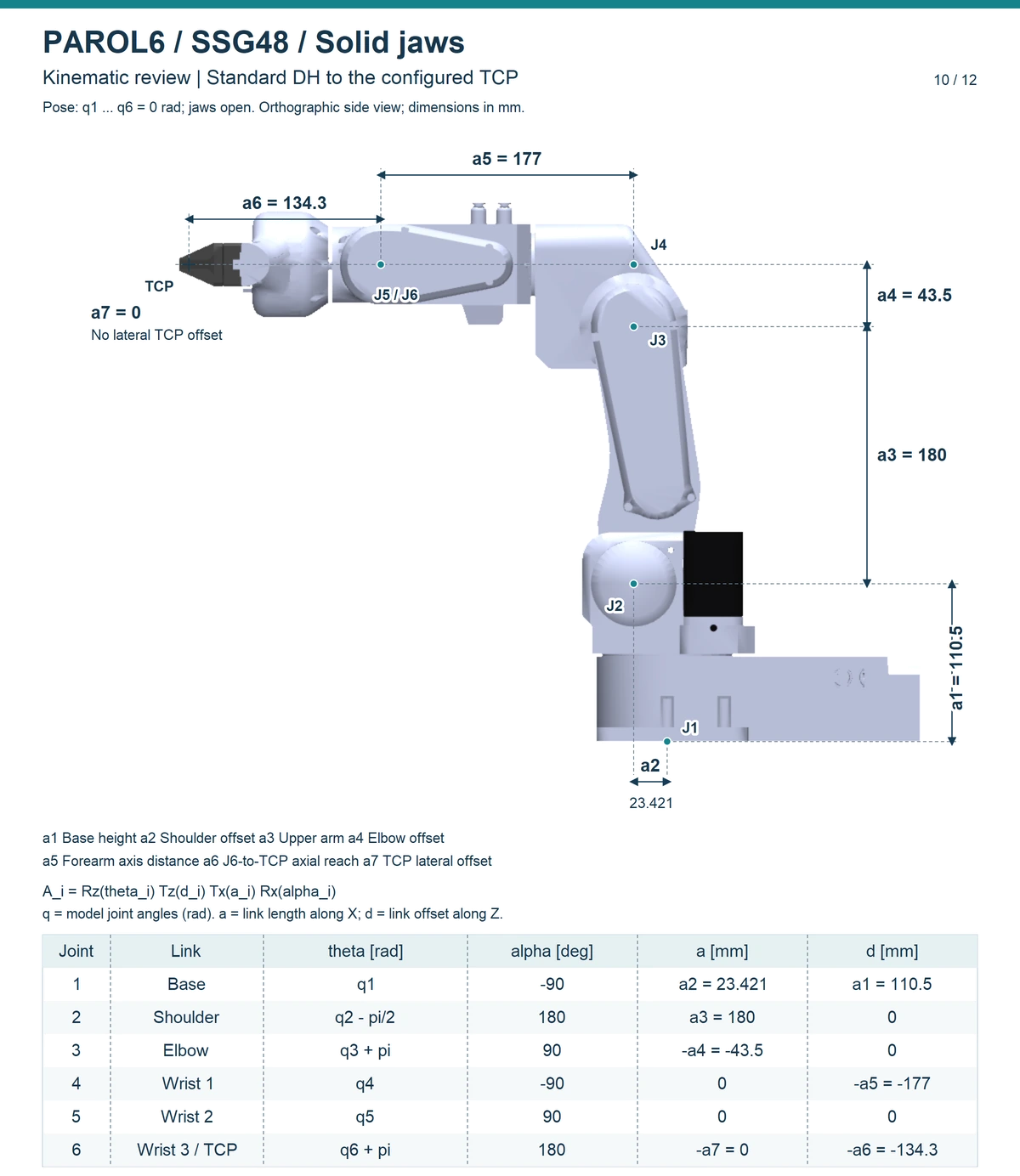
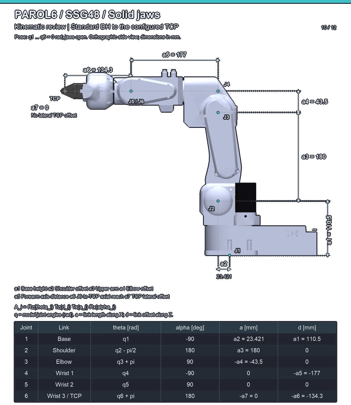
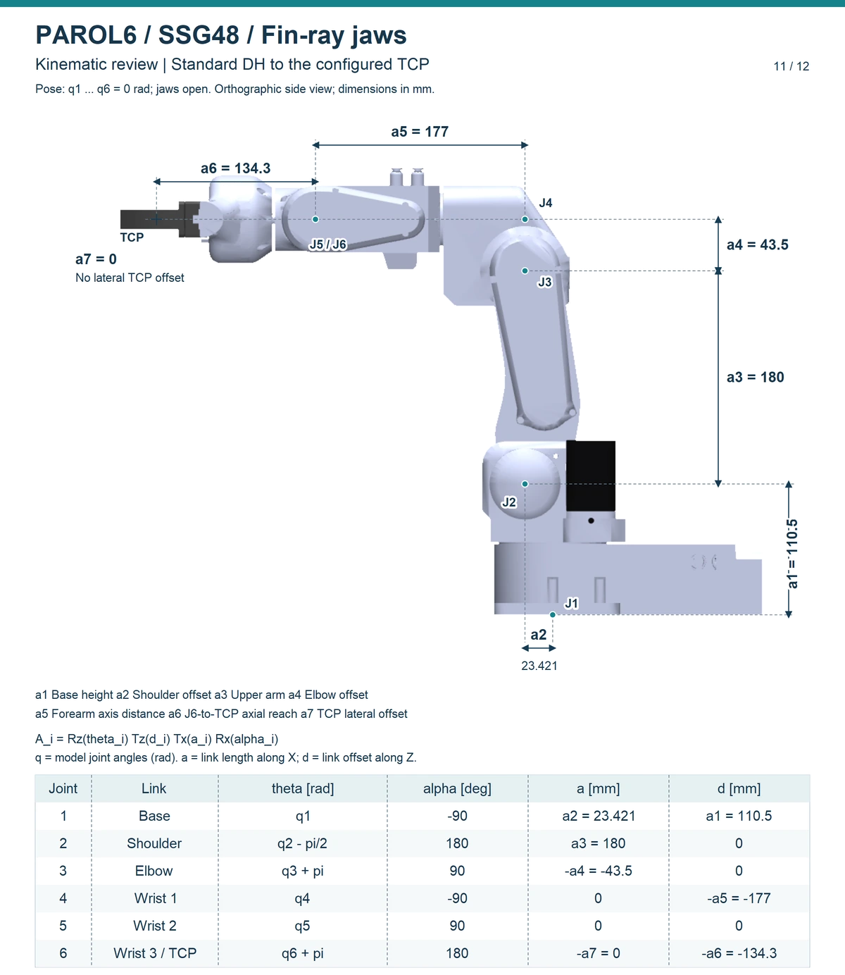
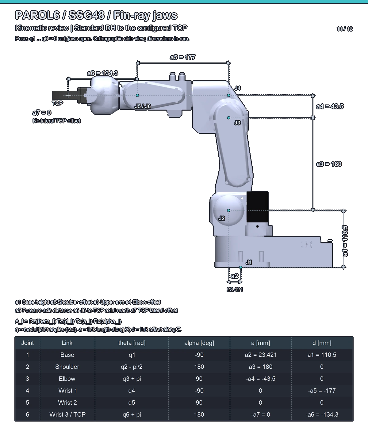
The sheets below come from PAROL6's models in robot_descriptions (version 2.15.1). Each shows the robot's own meshes in the standby pose (every joint of the model at 0), in one orthographic side view at one scale, with the dimensions taken from the URDF, not measured from the picture, and the standard DH table to the tool centre point (TCP) of that configuration. Click a sheet to enlarge it.
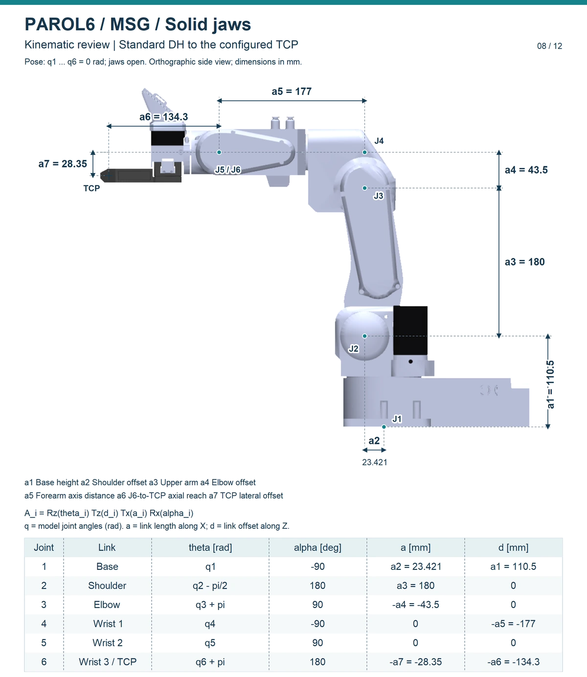
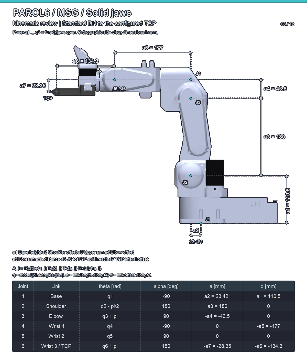
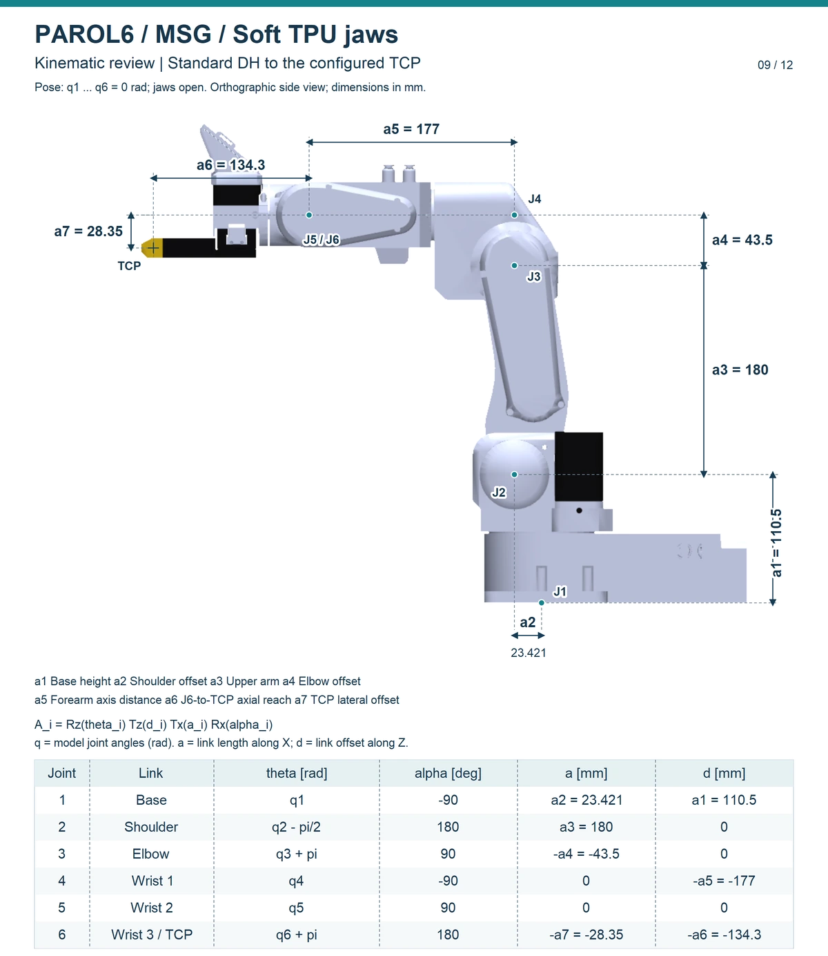
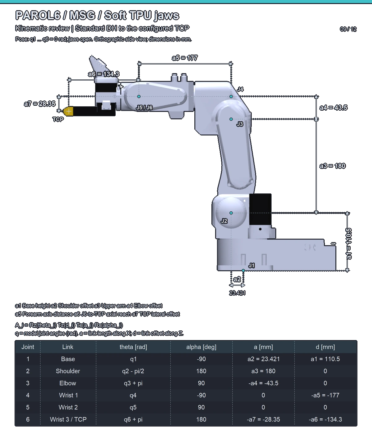
| Dimension | What it is | Value |
|---|---|---|
| a1 | Base height: the floor to the joint 2 axis | 110.5 mm |
| a2 | Shoulder offset: the joint 1 axis to the joint 2 axis | 23.42 mm |
| a3 | Upper arm: joint 2 to joint 3 | 180 mm |
| a4 | Elbow offset | 43.5 mm |
| a5 | Forearm: the joint 3 axis to the wrist centre | 177 mm |
| a6 | The joint 6 centre to the TCP, along the tool axis | depends on the tool, below |
| a7 | Sideways offset of the TCP | depends on the tool, below |
| Tool | a6 | a7 |
|---|---|---|
| Flange only (the TCP is the flange face) | 50.5 mm | 0 |
| Pneumatic gripper | 62.3 mm | 45.25 mm |
| SSG-48, solid or fin-ray jaws | 134.3 mm | 0 |
| MSG, solid or soft jaws | 134.3 mm | 28.35 mm |
A riser under the base changes a1, and a tool of your own changes a6 and a7: tell the software about the tool (Tools and the TCP), or the poses it reports will be wrong.
The software still computes with the earlier model
These pages give the model's dimensions. Until the software is updated, the Python API (its built-in URDF) and the commander software compute with a5 = 176.35 mm. The commander uses a6 = 62.8 mm for the pneumatic gripper, so a pose it reports can differ from these sheets by up to about 0.65 mm. The Python API has its own tool offsets, which put its TCP up to about 14 mm from the model's (The TCP of each tool).
Workspace
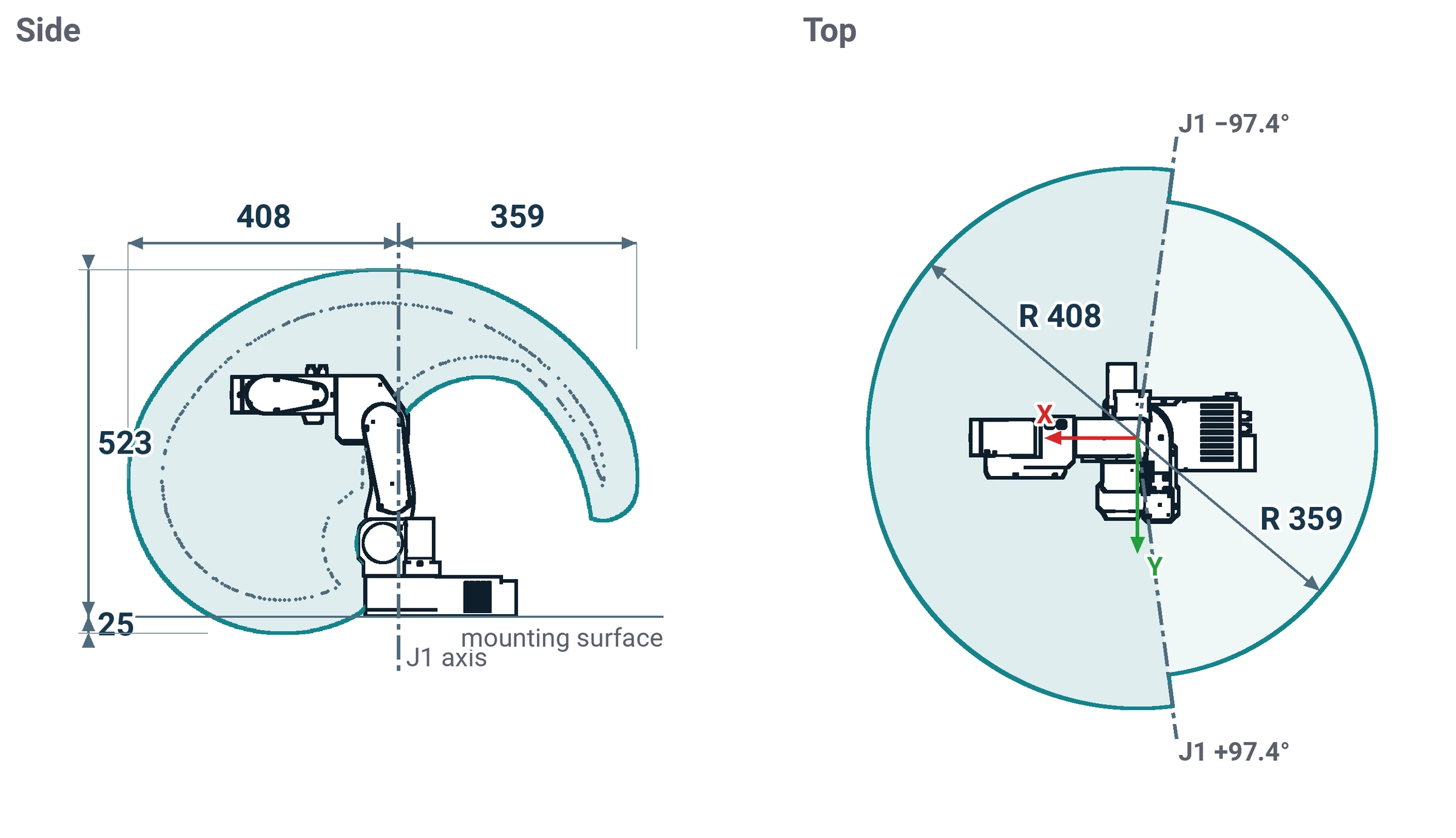
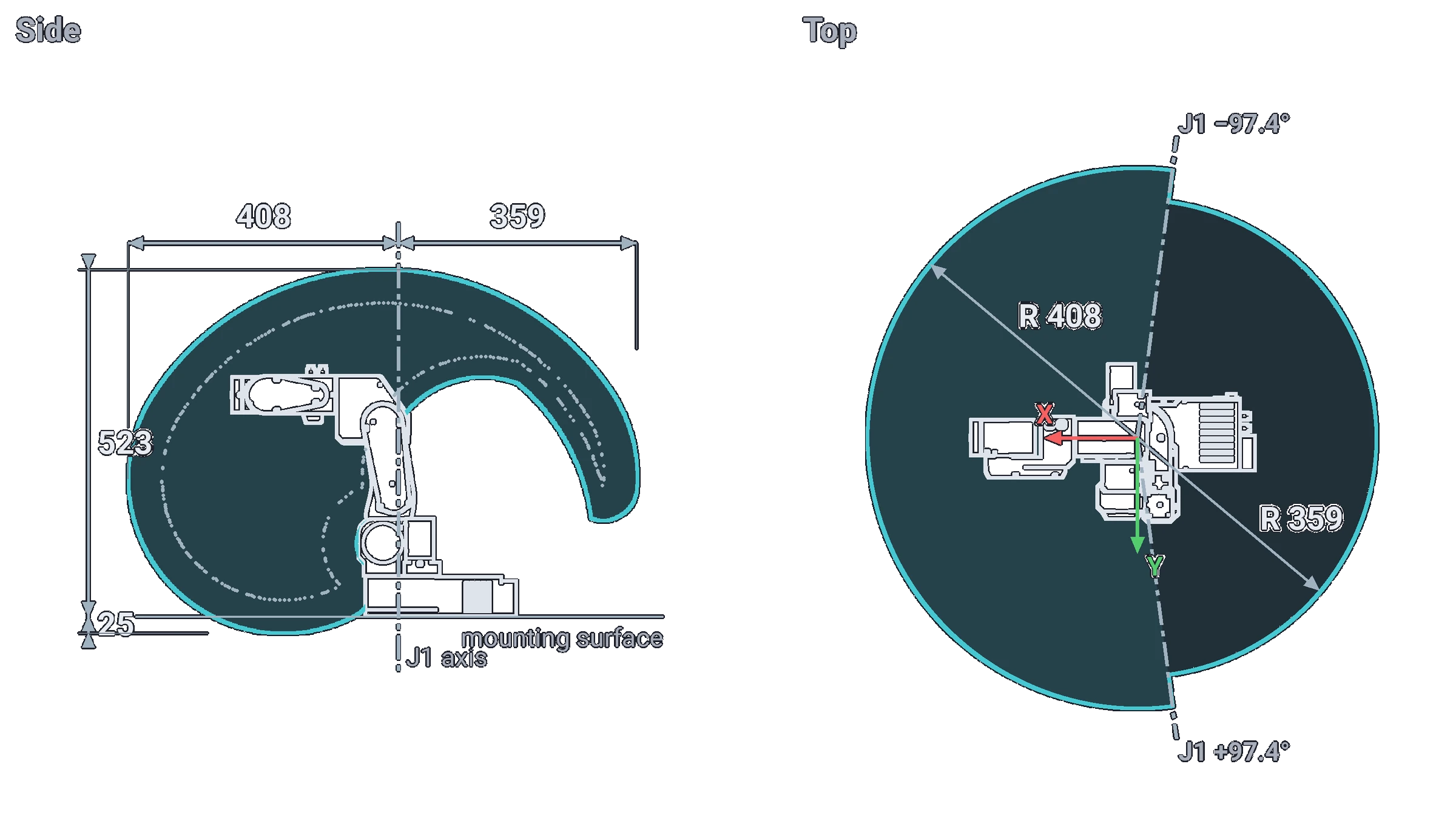
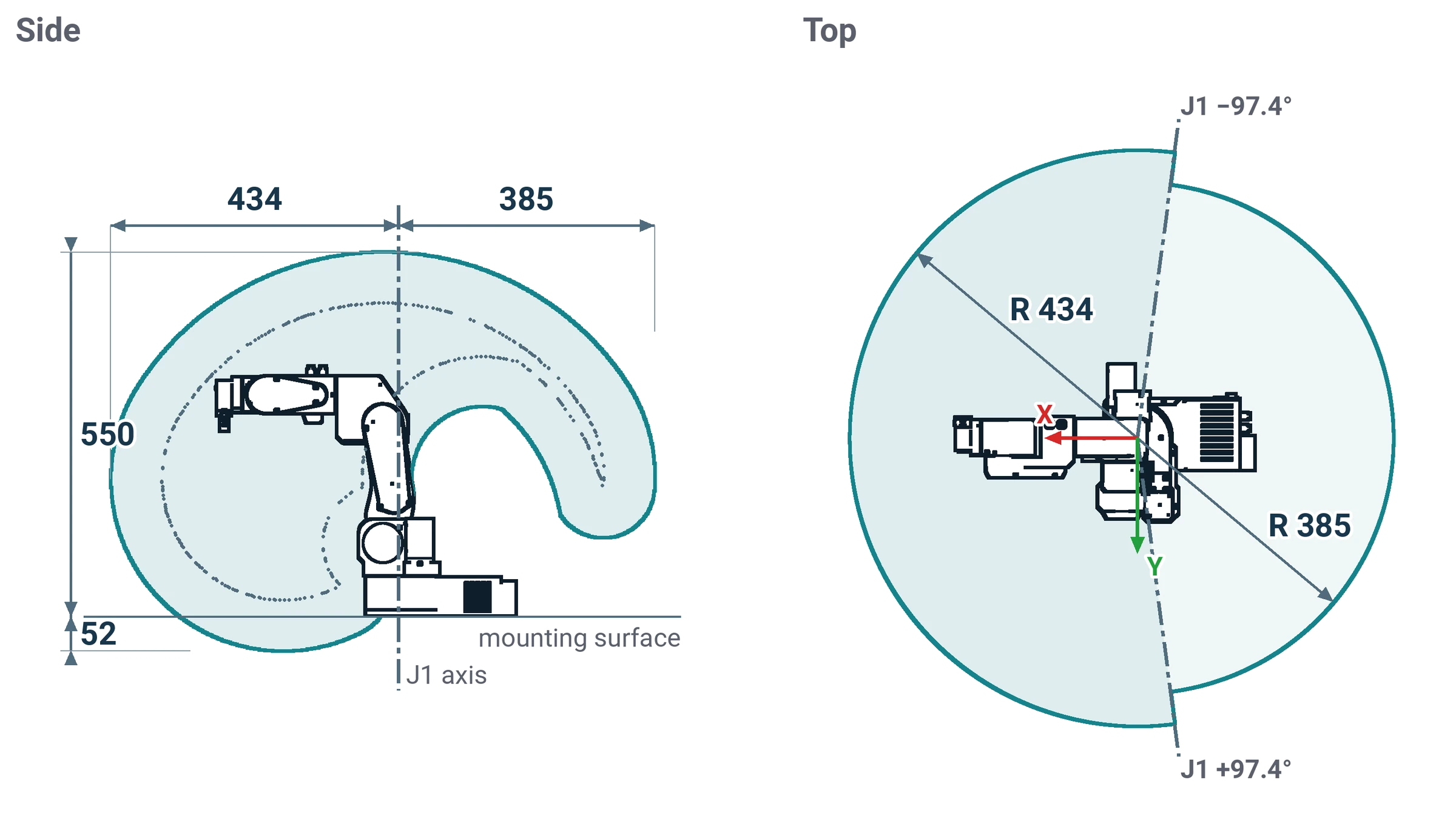
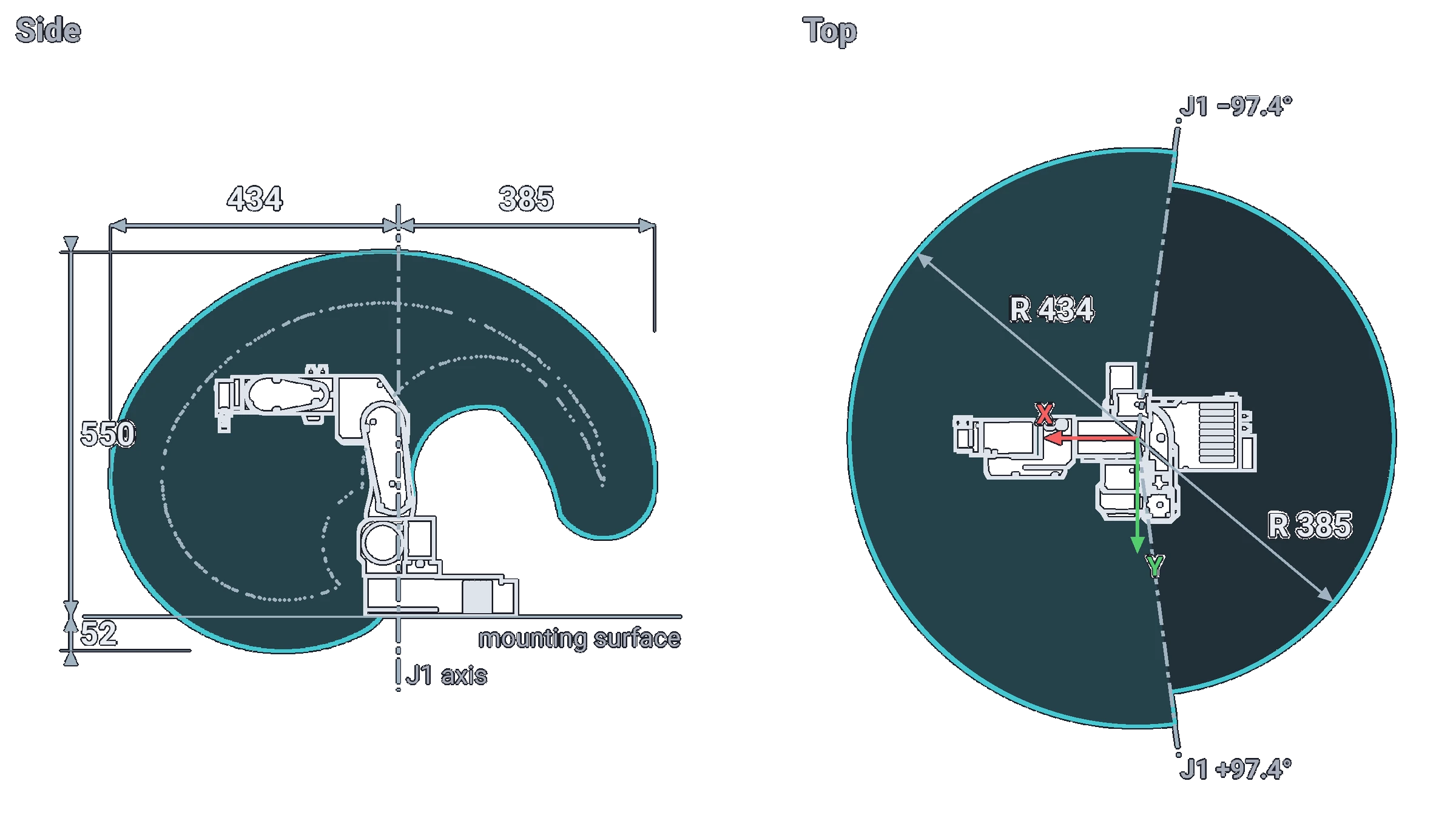
Where the tool centre point can go within the model's joint limits: on the left in the plane of the arm, on the right seen from above, as joint 1 turns through its range. Each tab is for one point: the flange centre, or the TCP of a gripper.
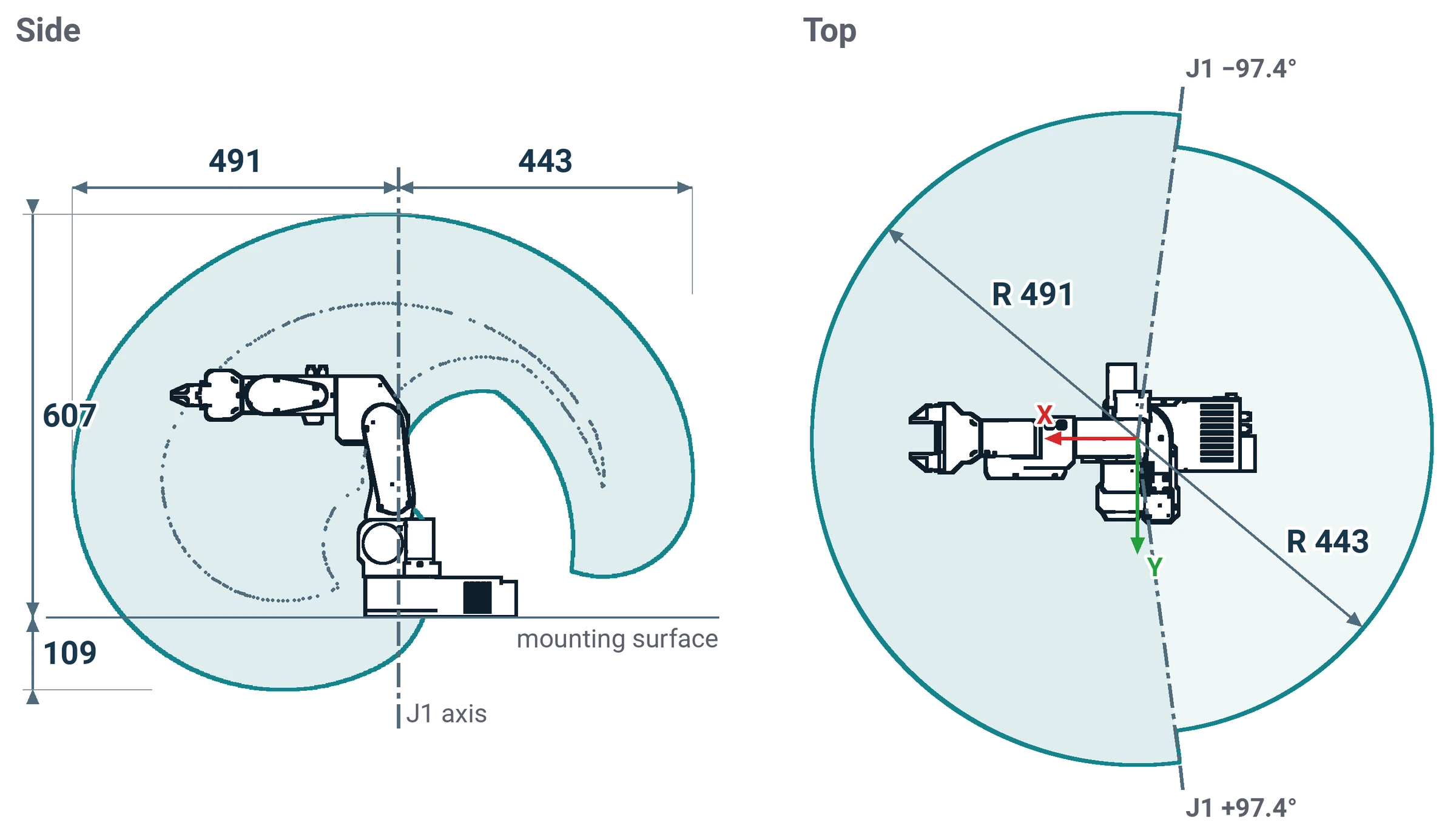
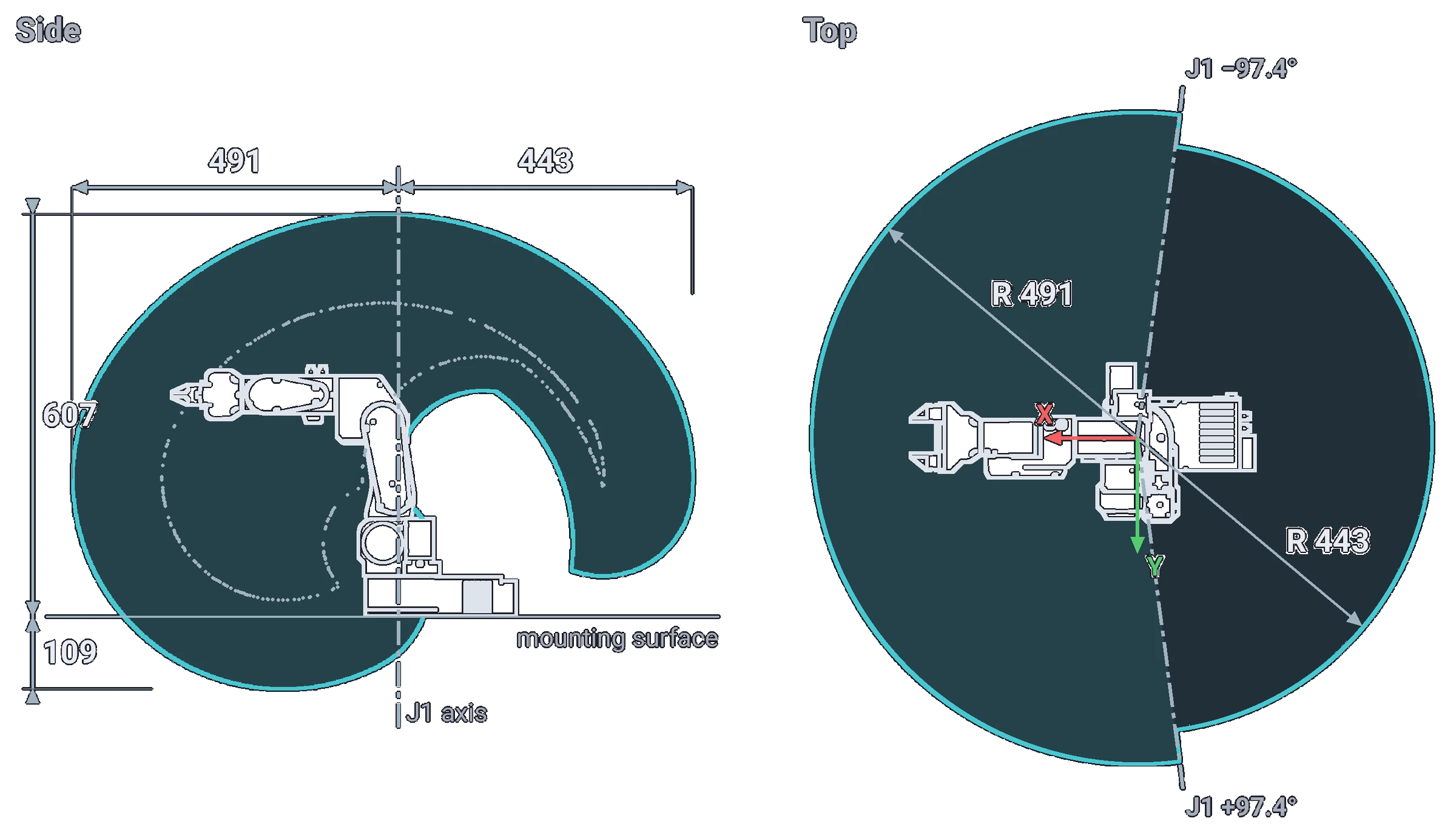
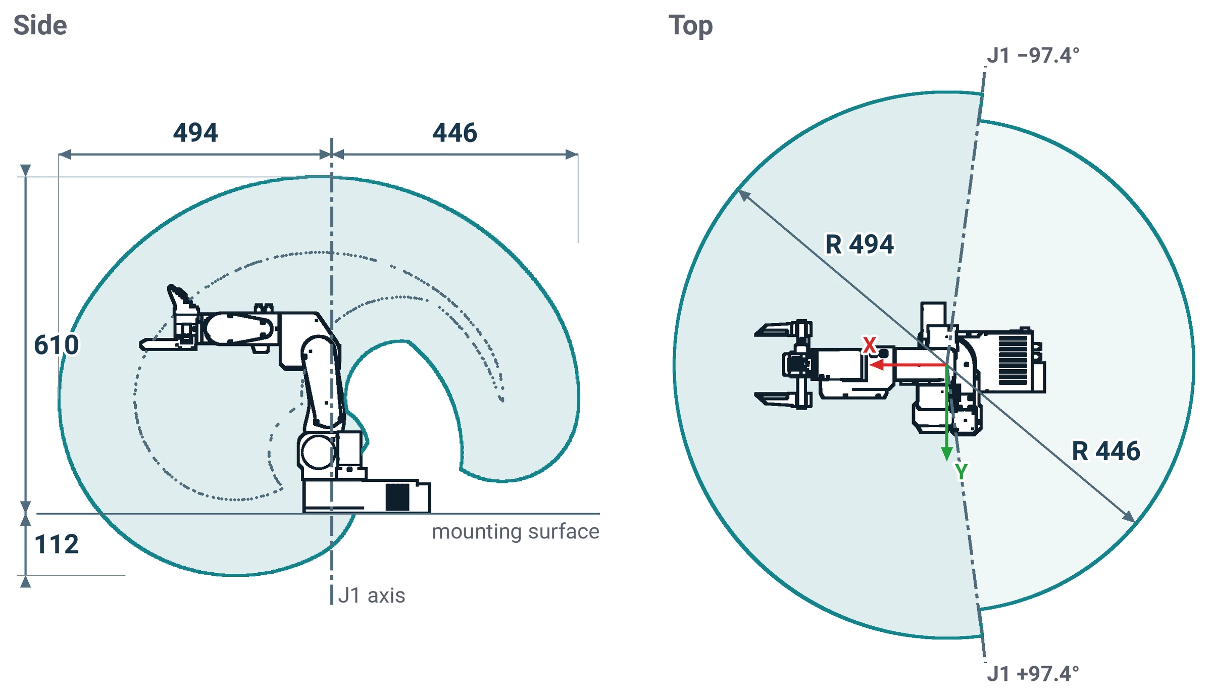
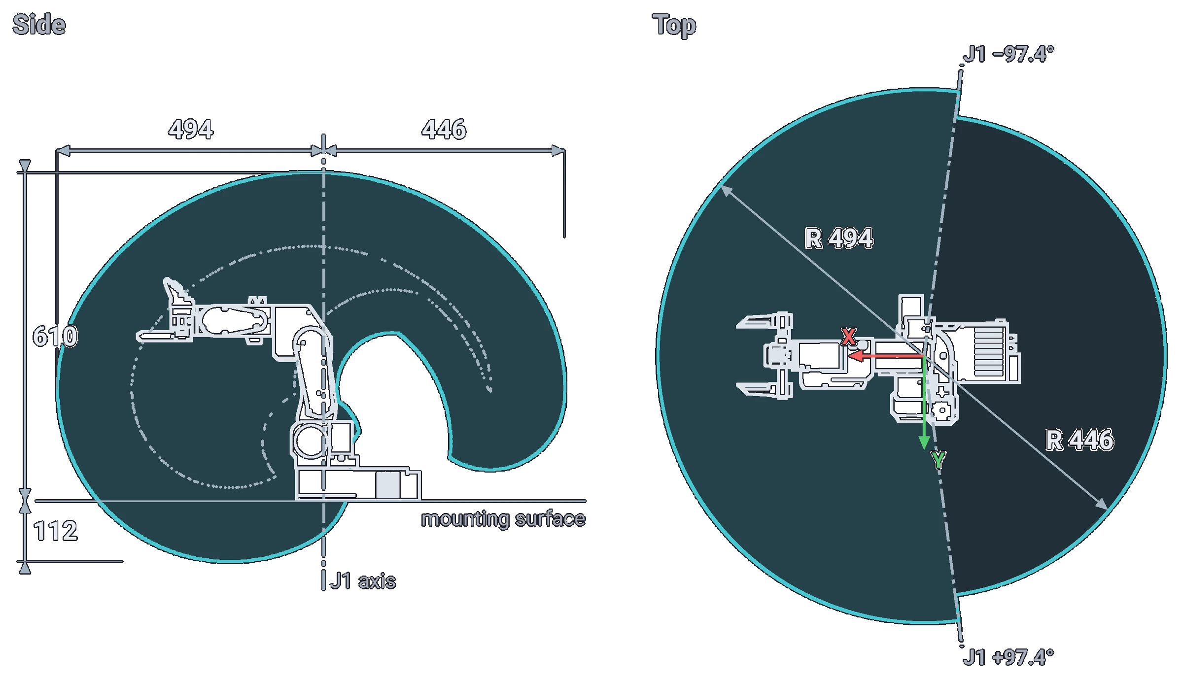
| Point | In front of the joint 1 axis | Behind it | Highest, above the mounting surface | Lowest |
|---|---|---|---|---|
| Wrist centre | 357 mm | 308 mm | 473 mm | 26 mm above |
| Flange centre | 408 mm | 359 mm | 523 mm | 25 mm below |
| Pneumatic gripper TCP | 434 mm | 385 mm | 550 mm | 52 mm below |
| SSG-48 TCP | 492 mm | 443 mm | 607 mm | 109 mm below |
| MSG TCP | 494 mm | 446 mm | 610 mm | 112 mm below |
In the side view the shaded region is where the point can go, with joints 2, 3 and 5 anywhere within their limits, joint 4 at 0° and joint 6 at 0° or 180°, so that a TCP beside the tool axis stays in the plane; the dotted line is the same for the wrist centre. The region shows where the point can go, not where the tool can take every orientation: at its edge the tool can only point outwards (Workspace and reach). It is computed from the joint limits only: the arm's own parts, the tool and the table can block some of it.
- Below the mounting surface. The region dips below the surface the robot stands on, in front of the base. On a table that part is solid; the arm reaches it only past the table's edge, or with the robot on a riser.
- Behind the base. Joint 1 turns ±97.4°, so seen from above the arm reaches a little more than the half circle in front of it. The lighter part behind the base it reaches only by folding back over the base, the way the side view's region curls behind the joint 1 axis.
- Near the joint 1 axis. Keep the work away from it. With the wrist centre on the joint 1 axis the arm is in its shoulder singularity, and close to it joint 1 has to turn fast for a small move of the tool (Configurations and singularities).
- X and Y in the top view are the axes of the world frame: X is the way the arm points in the standby pose, Y the way it points after homing (Reference frames).
Kinematic structure
The first three joints place the wrist centre; the axes of joints 4, 5 and 6 intersect in one point, a spherical wrist, which is what makes the inverse kinematics tractable. The Theory corner explains forward and inverse kinematics, and Configurations and singularities the eight ways the arm can reach one pose.
Denavit-Hartenberg parameters
Standard DH, each joint's transform being A_i = Rz(theta_i) Tz(d_i) Tx(a_i) Rx(alpha_i), from the base to the
TCP. q1 to q6 are the model's joint angles (the URDF's), all 0 in the standby pose; the theta column already
contains the joint offsets, so do not add them twice. Theta is the angle the software shows: joint 2's software
angle is q2 − 90°, joint 3's is q3 + 180° and joint 6's is q6 + 180°, the others are equal. The sheets above give
the same table for each tool.
| Joint | Link | theta | alpha | a | d |
|---|---|---|---|---|---|
| 1 | Base | q1 | -90° | a2 = 23.42 mm | a1 = 110.5 mm |
| 2 | Shoulder | q2 - 90° | 180° | a3 = 180 mm | 0 |
| 3 | Elbow | q3 + 180° | 90° | -a4 = -43.5 mm | 0 |
| 4 | Wrist 1 | q4 | -90° | 0 | -a5 = -177 mm |
| 5 | Wrist 2 | q5 | 90° | 0 | 0 |
| 6 | Wrist 3, to the TCP | q6 + 180° | 180° | -a7 | -a6 |
The models were checked at 128 poses including the joint limits: the DH table, the URDF and the MuJoCo model agree to within 0.006 mm and 0.002°. The Python API does not use the table directly: it loads its URDF and computes the kinematics numerically. The commander software uses a Robotics Toolbox DH model.
Mounting holes
Six holes in the base, on a pattern made for 30×30 mm aluminium profiles. The mounting plates folder of the repository has STEP drawings of a small and a big base plate: Mounting the robot.
Comments
Found a mistake on this page? Edit it on GitHub · Report it · Get help · This page as Markdown · llms.txt · The whole manual as PDF