10. The serial protocol
The PC and the board exchange one packet each per control cycle over USB, a virtual serial port (the PC software opens it at 3 000 000 baud, a setting USB ignores). The PC sends a command packet at 100 Hz; the board answers each valid packet with a telemetry packet. Both are binary, framed with start bytes, a length byte, two end bytes and a CRC byte, and together under 120 bytes. The byte-exact layout is on The serial protocol in the API reference; this page explains how it works.
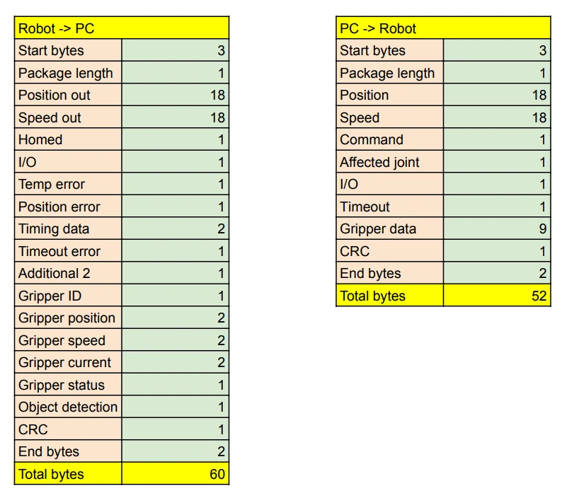
The cycle
loop:
    read the power button; run the active command (jog, go-to-position, home, idle)
    while serial data is available:
        read a byte; look for the three start bytes 0xFF 0xFF 0xFF
        the next byte is the length: that many bytes follow, including the CRC and the end bytes
        when the end bytes are 0x01 0x02: unpack the packet into the commanded positions, speeds, command,
            outputs, gripper fields; read the E-stop and inputs; write the outputs; send the gripper its frame;
            pack and send the telemetry packet
A valid packet starts one robot cycle: the firmware does nothing on its own between packets except run the
speeds it was last given. The PC must keep the packets coming; the time between the last two packets is measured
with a 703 125 Hz timer (90 MHz / 128, so 1.422 µs per tick: 10 ms is 7031 ticks) and returned in the telemetry
as timing_data, which is how the PC software checks that it keeps the 100 Hz loop.
Commands
The command byte selects what the board does with the carrier data (the positions and speeds) in the same packet:
| Command | Name | What the board does |
|---|---|---|
| 255 | Idle (dummy) | The joints stand still: it sets their speeds but steps none; it only continues a homing in progress. The default between moves |
| 123 | Jog | Runs each joint at its commanded speed (runSpeed) |
| 156 | Go to position with speed | Runs each joint at the average of its commanded speed and the speed that would close the position error in one cycle: the tracking the planners use |
| 100 | Home | Starts the homing sequence; idle packets continue it until done |
| 101 | Enable | Enables the robot and resets the homing state |
| 102 | Disable | Disables motion commands; the motors keep holding |
| 103 | Clear error | Resets the homing state |
| 69 | Repeatability test | A built-in two-pose cycle, for testing |
Motion commands (100, 123, 156) are ignored while the robot is disabled. A jog or go-to packet ends a homing in progress; the homed bits in the telemetry change only by homing. The firmware does not check them before a move: the PC decides when a move is allowed.
Passive data
The I/O byte carries the two output states in every packet, and the gripper fields (ID, position, speed, current, command bits, mode) are forwarded to the gripper over CAN every cycle: a move when they change, a calibrate for mode 1, a clear-error for mode 2, and an empty status poll when nothing changed. They ride along with any command.
Telemetry
The board returns the six positions and speeds in motor steps, which joints are homed, the inputs, outputs and E-stop, two bytes of driver flags (temperature and position, reserved: the joint bits are cleared and the two spare bits set), the timing, the last command byte it received, and the gripper's data. Of that, the gripper reports only its position, current and status byte; the ID, speed and object-detection bytes are fixed values, and the object detection is read from two bits of the status byte (The serial protocol).
Writing your own host
Anything that frames the packets as on the reference page and keeps the 100 Hz cadence can drive the board: the commander software and the Python API are two such hosts, in Python. Start from the Python API's serial transport rather than from scratch; the Control ownership page says why two hosts must not talk to the board at once.
Comments
Found a mistake on this page? Edit it on GitHub · Report it · Get help · This page as Markdown · llms.txt · The whole manual as PDF