6. Inputs, outputs and E-stop
The isolated I/O
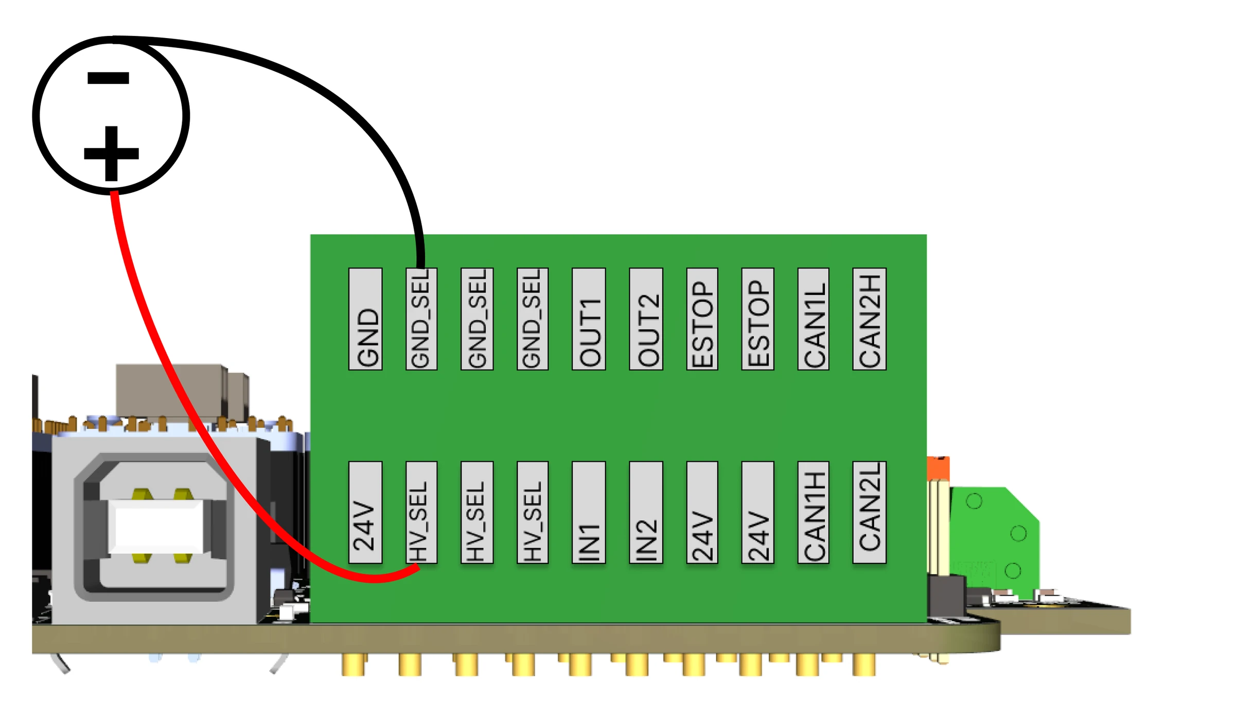
Two inputs and two outputs on optocouplers, with their own supply rails HV_SEL and GND_SEL on the terminal blocks. You decide what feeds those rails:
An external supply's negative to GND_SEL, positive to HV_SEL. The I/O then runs at that voltage, 24 V nominal and at least 12 V for the inputs, and a short or a surge on a sensor cannot reach the robot's electronics.
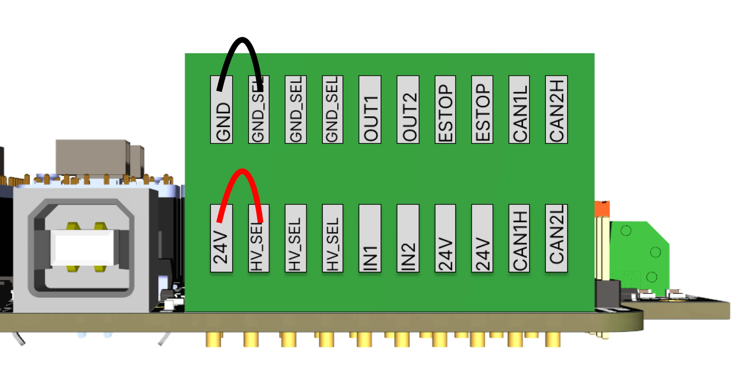
Link the board's 24 V and GND terminals to HV_SEL and GND_SEL. The I/O shares the robot's supply, with a 2 A fuse protecting the outputs. Simpler, and enough for a pneumatic valve.
The E-stop is on the robot's own supply in both cases.
Inputs
Between HV_SEL and IN1 or IN2: a switch, a push button, a relay contact, or the signal of a sensor fed from HV_SEL and GND_SEL. 12 to 50 V. The firmware reads them every cycle and reports them in the I/O byte of the packet.
Outputs
Between GND_SEL and OUT1 or OUT2: a relay coil, a valve, a lamp. 0.5 A continuous, 1 A peak, 48 V maximum, with a flyback diode across any coil. The firmware sets them from the I/O byte of the PC's packet.
The E-stop
Two connectors on the same input, for a normally closed contact. The firmware reads the input every cycle and reports it in the I/O byte; the PC software stops the robot when it sees the contact open (Emergency stop).
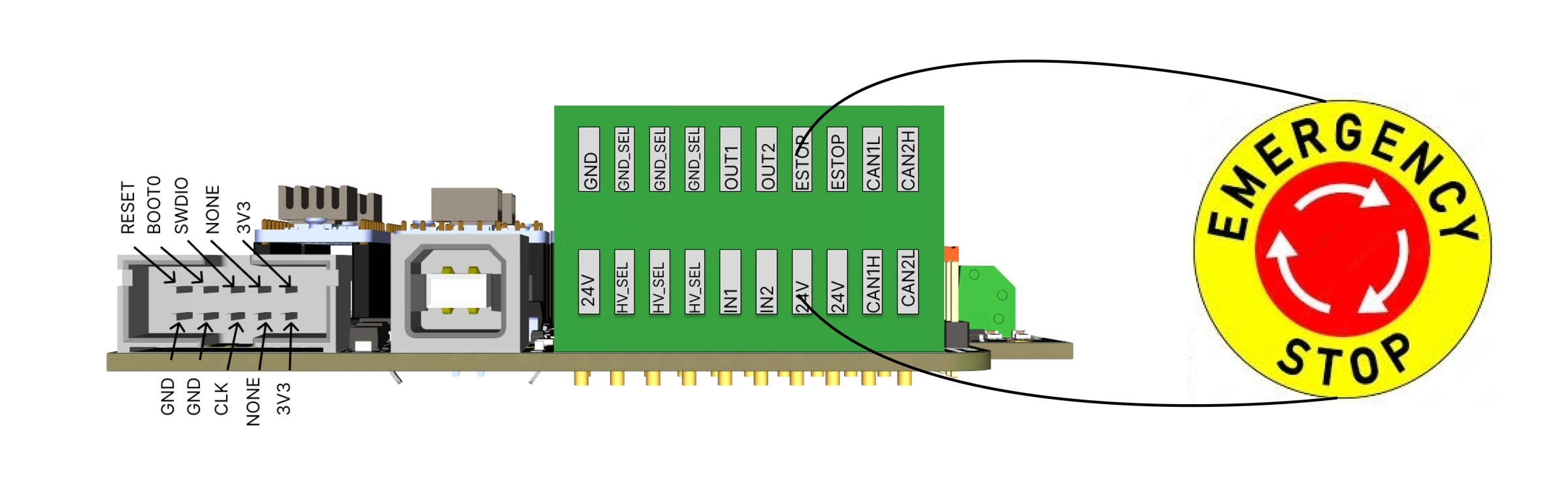
- The contact must be normally closed: an open circuit means stop, so an unplugged button or a cut wire stops the robot too. A normally open button does not work.
- Both connectors share one microcontroller pin: a second button goes in series on the other connector.
- Any NC switch works for a bench setup. The BOM's 19 mm E-stop and the printed housing go on the base.
The power button
A momentary push button with an LED, on the JST PH connector. A press switches the 24 V stage on; a press while on switches it off. The LED is fed from the button connector. The firmware reads the button on every pass of its main loop.
Comments
Found a mistake on this page? Edit it on GitHub · Report it · Get help · This page as Markdown · llms.txt · The whole manual as PDF