9. The test firmware
The test firmware turns the board into a bench instrument. At power-on it checks the six stepper drivers over SPI and prints the result, then turns all six motors slowly, blinks the LEDs and toggles the two outputs; on request it prints the E-stop, the inputs, the supply voltage and the limit switches over USB. It is what every board ships with, and the right tool for a freshly wired robot before the base is closed.
The motors turn as soon as it starts
The test firmware enables all six drivers when it boots and turns every motor slowly, at 1000 steps per second,
without being asked, with no limits and no homing, until the power is switched off. No command stops them:
#STOP only ends a printout. Use it with the arm free to move or the motors unmounted, never on a robot folded
against its stops.
Connecting
Upload the firmware if the board does not have it (Firmware), then open a serial terminal on the
board's USB port: PlatformIO's monitor, PuTTY or screen. The board is a USB device, so the baud rate does not
matter; PlatformIO's monitor uses the 3000000 set in the project's platformio.ini. Make the terminal send a line
feed at the end of each line: the firmware acts on a command only when the line feed arrives, so a terminal that
sends only a carriage return on Enter gets no answer. Two ways to power the board for the test:
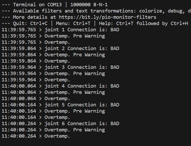
- the programming adapter's 3.3 V, with the 24 V supply disconnected: the board talks, but the drivers have no power and report errors;
- the 24 V supply: the board is off until you press the power button, or supply 3.3 V from the adapter as well.
What it does by itself
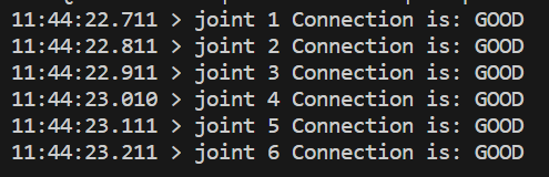
- About three seconds after power-on it reads every driver over SPI and prints a report per joint:
joint N Connection is: GOODorBAD, then the driver's current, hold and run current settings and its fault flags. - From then on all six motors turn slowly and keep turning.
- Every second the two LEDs blink and outputs 1 and 2 toggle.
Commands
# followed by the name, case as written, and the line feed. Four commands do something:
| Command | What it does |
|---|---|
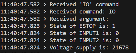
#IO |
Prints, once a second, the E-stop input, input 1, input 2 and the supply voltage in millivolts |
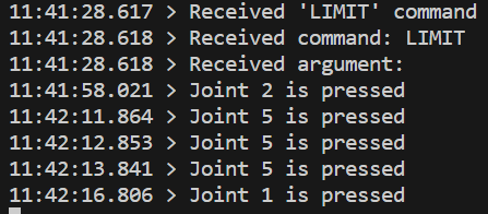
#LIMIT |
Prints, once a second, Joint N is pressed for every limit switch that is triggered, numbered by joint |
#STOP |
Ends the #IO or #LIMIT printout; the motors keep turning |
#start |
Toggles the two LEDs |
Every other name, including #STATUS, #STEP1 to #STEP6, #FLASH and #CAN, is answered with Unknown
command: the parser knows the names, but the firmware does nothing with them. Test firmware
commands is the reference list.
Testing CAN
CAN has its own test, next to the test firmware in the repository's PAROL6 control board test code folder and not
part of its build: the sketch can_12_12 sends a frame with ID 0x446 every 500 ms at 1 Mbit/s and prints every
frame it receives, and can_parol6_test.py is the PC side, a python-can script for a USB-CAN adapter (slcan, 1
Mbit/s; set its port, COM44 in the file) that prints the frames it receives with their node and command IDs.
What good looks like
All six drivers answering, in the report at power-on:
A driver missing or faulty:
With good drivers and the 24 V on, the motors turn slowly at 200 to 300 mA. A triggered limit switch, with
#LIMIT:
The I/O report, with #IO; change the E-stop or an input and the values follow:
Outputs 1 and 2 toggle every second, and the two LEDs blink.
Comments
Found a mistake on this page? Edit it on GitHub · Report it · Get help · This page as Markdown · llms.txt · The whole manual as PDF