Mounting on a robot
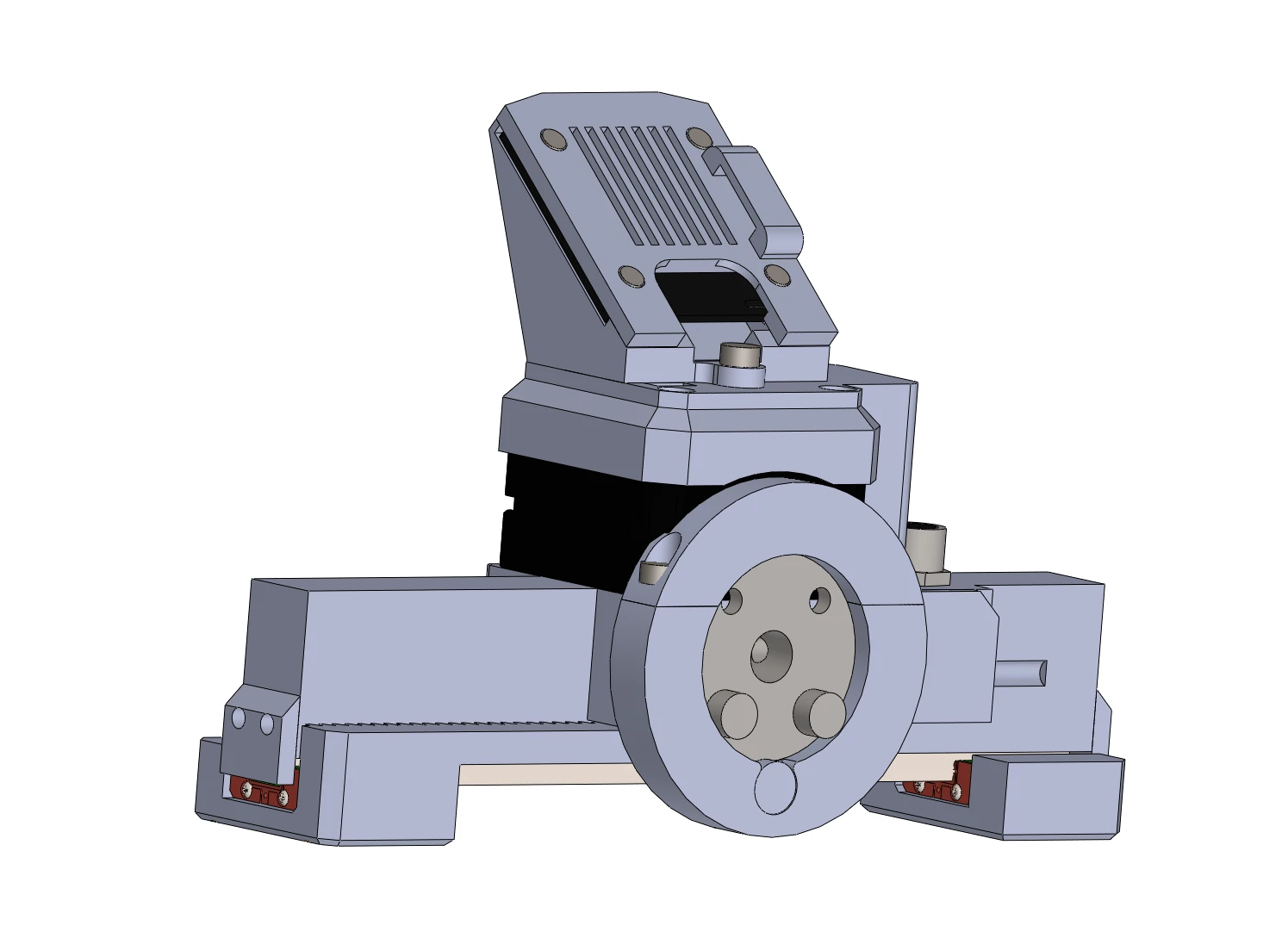
The gripper mounts by its coupler plate, the round plate on the back of the body behind the stepper. Two covers exist for it, and the STEP files let you make a third.
An 8 mm shaft
As shipped, the coupler plate carries a shaft coupler with an 8 mm bore and M4 clamp screws under the ring_cover
part: the gripper slides onto an 8 mm shaft and is clamped with the two M4 screws. Any robot or fixture that
offers an 8 mm shaft takes the gripper this way.
PAROL6
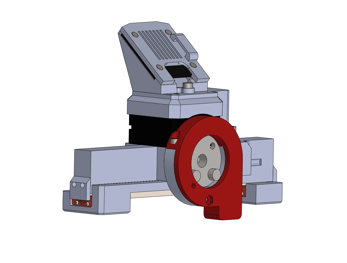
For the PAROL6 wrist, replace ring_cover with ring_cover-PAROL6 from the STEP files (Common parts): it bolts
to the robot's last joint. Tighten the shaft coupler's two clamp screws with blue threadlocker. The PAROL6
gripper cable then runs from the gripper to the robot's gripper port; see The cable and
On PAROL6 and PAR6, which also has the joint 5 homing offset.
Another robot
Adapt ring_cover, or the body itself, to your flange: the STEP files are open. Keep the gripper's connector
reachable and the camera's view free, and route the cable so that it cannot be pulled by the robot's motion.
On the bench
For testing, clamp the body, not the jaws or the rail, and leave the whole stroke free: calibration moves the jaws from one end stop to the other without any command from you.
Comments
Found a mistake on this page? Edit it on GitHub · Report it · Get help · This page as Markdown · llms.txt · The whole manual as PDF