Connector and pinout
The gripper has one connector, an M8 4-pin male on the side of the body, and one cable: 24 V and the CAN bus.
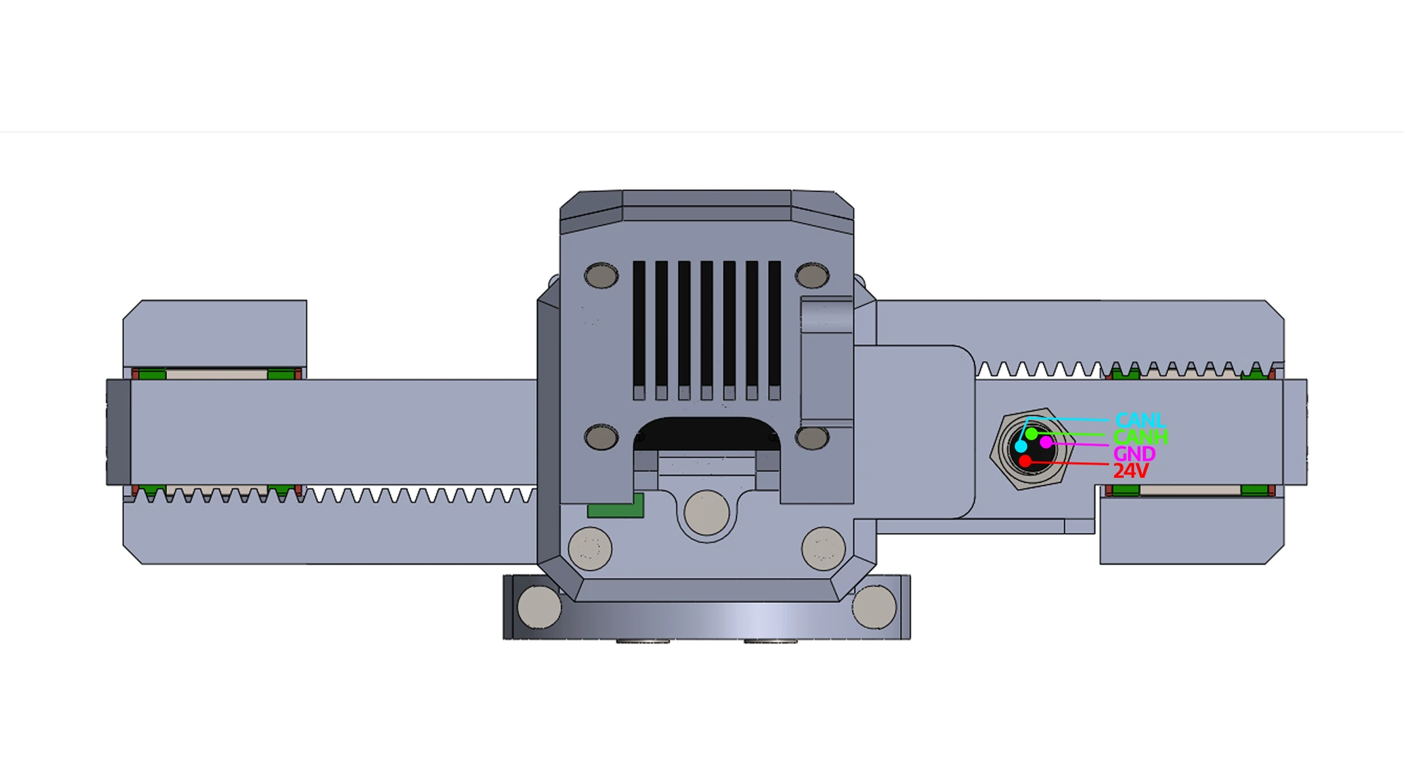
Pin numbers
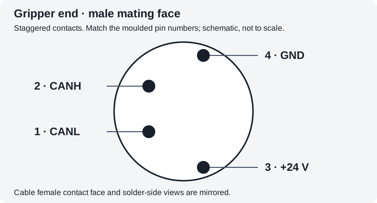
The drawing shows the connector's staggered contact layout. Look into the male connector on the gripper, with its pins visible. The female cable connector has the mirrored contact view. The solder side is also mirrored: use the numbers moulded into the connector, rather than matching wire colours or the installed housing's rotation.
| Gripper pin | Signal | Connection |
|---|---|---|
| 1 | CANL | CAN low |
| 2 | CANH | CAN high, 1 Mbit/s with CANL |
| 3 | +24 V | positive motor supply |
| 4 | GND | power-supply return |
These pin numbers combine the gripper's signal drawing above with the male contact numbering in the repository's cable drawing. They describe the gripper end. PAROL6 and PAR6 use different connections at the robot end: The cable gives both diagrams. Check continuity with the supply disconnected.

The wrong cable destroys the driver
A cable with 24 V on a CAN pin destroys the driver inside the gripper the moment it is powered. Use the cable made for your robot; check a self-made cable pin by pin against the pin table above and the wiring diagram before you plug it in.
Inside the housing
The STEPFOC driver's own connectors are inside: its UART port (3.3 V, JST SH, 4 pins) under the coupler plate, used to configure a self-built gripper (Over UART), and its CAN termination switch, reachable through an opening in the stepper cover (CAN termination). The driver's pinout is in the STEPFOC documentation.
Comments
Found a mistake on this page? Edit it on GitHub · Report it · Get help · This page as Markdown · llms.txt · The whole manual as PDF