Connectors and pinout
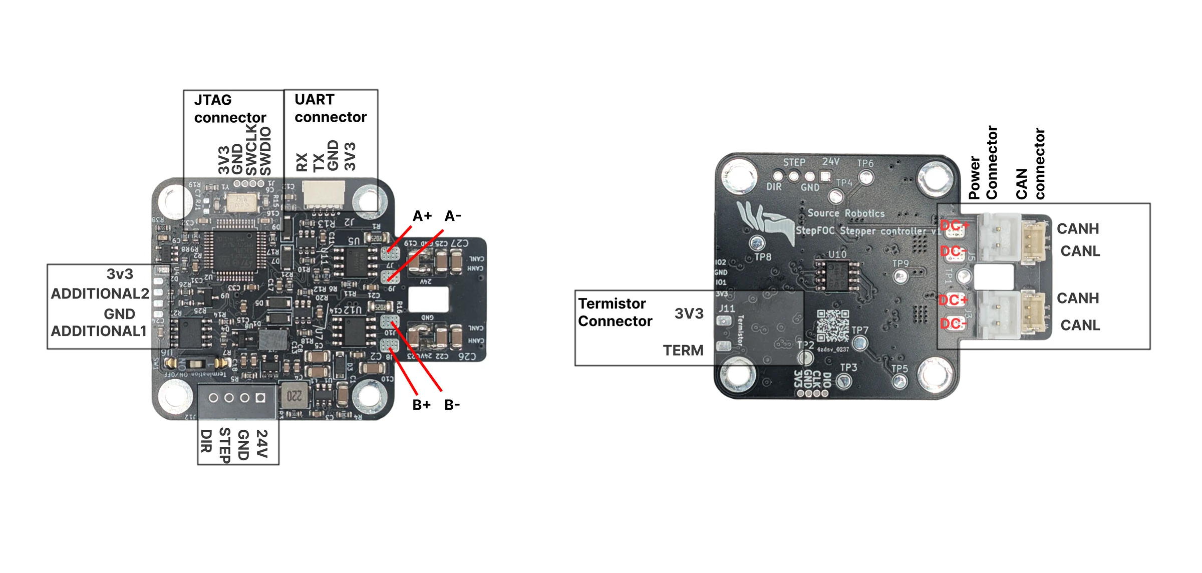
| Connector | Pins | Type | Cable |
|---|---|---|---|
| Motor | A+, A−, B+, B− | solder pads | the motor's own leads, see Wiring the stepper |
| Power, two of them | DC+, DC− | JST XH, 2 pins | Power cable; the second connector feeds the next driver |
| CAN, two of them | CAN L, CAN H | JST ZH, 2 pins | CAN cable; the second connector feeds the next driver |
| UART | 3.3 V, TX, RX, GND | JST SH, 4 pins | UART cable |
| Thermistor | NTC, NTC | JST SH, 2 pins | the 100 kΩ NTC from the shop or any 100 kΩ NTC |
| JTAG | 3.3 V, GND, SWCLK, SWDIO | pads, 1.27 mm pitch | Programming adapter, pressed onto the pads; the order is marked in Installing the bootloader |
| ADDITIONAL2 | signal, GND | pads | your sensor; the HALL homing mode reads this pin |
| STEP / DIR | STEP, DIR, GND, 24 V | header | hardware only: the firmware does not support a step/dir interface |
Polarity and orientation
DC+ to the positive supply, DC− to the negative; a cable the wrong way round destroys the driver. The daisy-chain cables have an orientation too: see Power and the CAN daisy chain.
Note
- UART is TX to RX and RX to TX between the driver and the adapter.
- The UART port and the ADDITIONAL2 pin are 3.3 V. 5 V on either destroys the board.
- The thermistor pin has a 54.9 kΩ pull-down; the firmware's temperature table is for a 100 kΩ NTC.
- The CAN termination switch is next to the CAN connectors; ON connects the 120 Ω resistor.
Comments
Found a mistake on this page? Edit it on GitHub · Report it · Get help · This page as Markdown · llms.txt · The whole manual as PDF