Dimensions and CAD
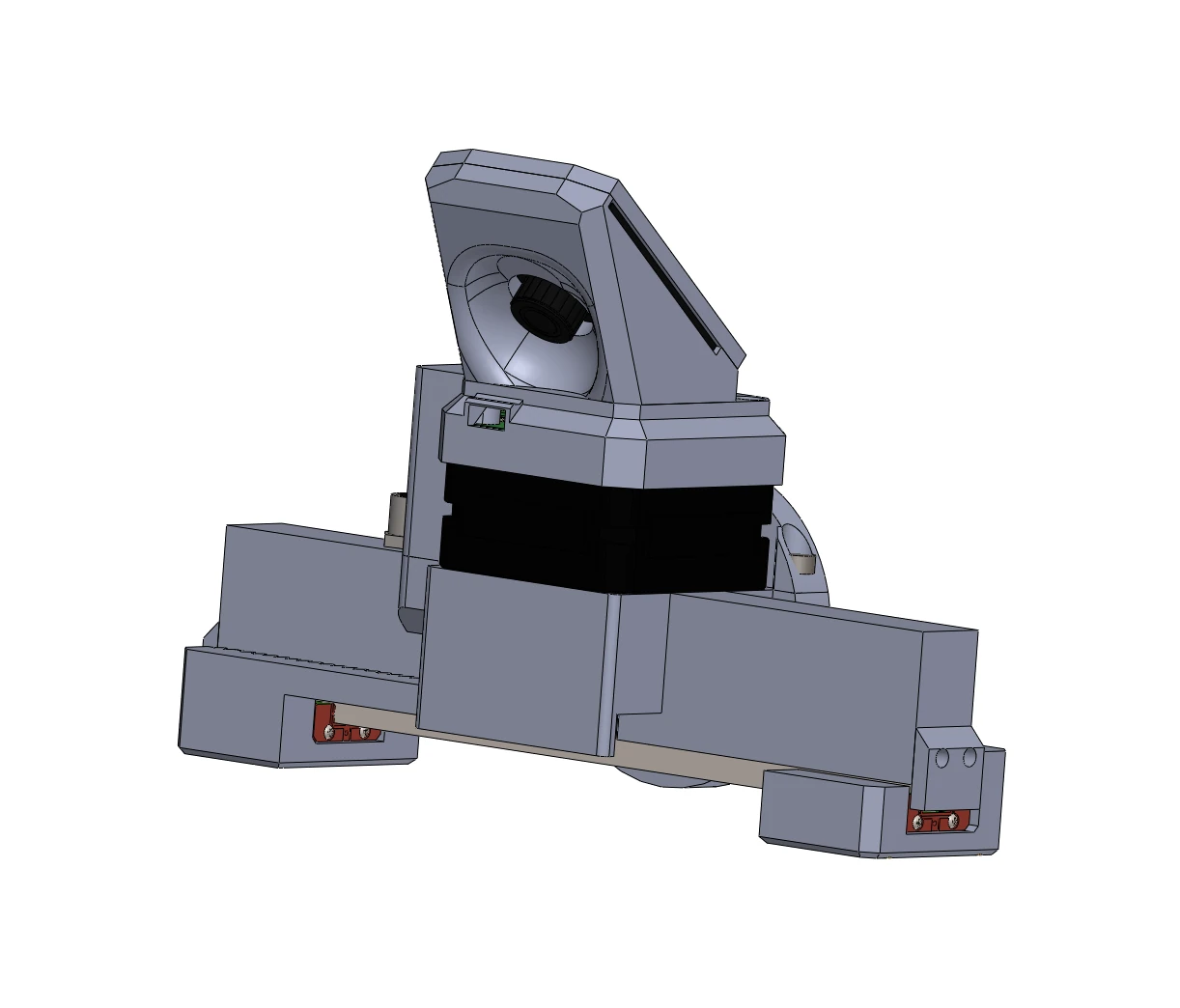
Drag to turn the gripper, scroll to zoom, open and close the jaws, try the colours. The model is the gripper's URDF, the 150 mm rail with the 21.5 mm stepper; the current URDF and MuJoCo models are linked from the repository's msg_description guide. The shop sells the body in black and grey.
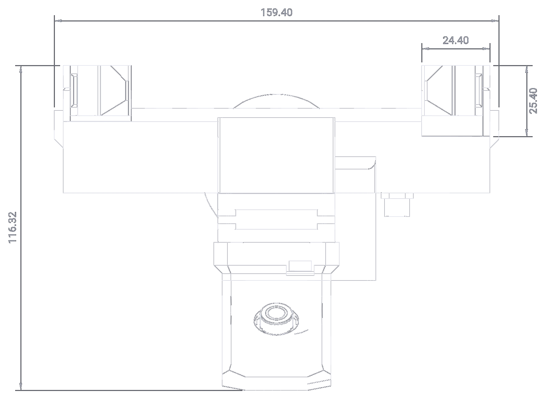
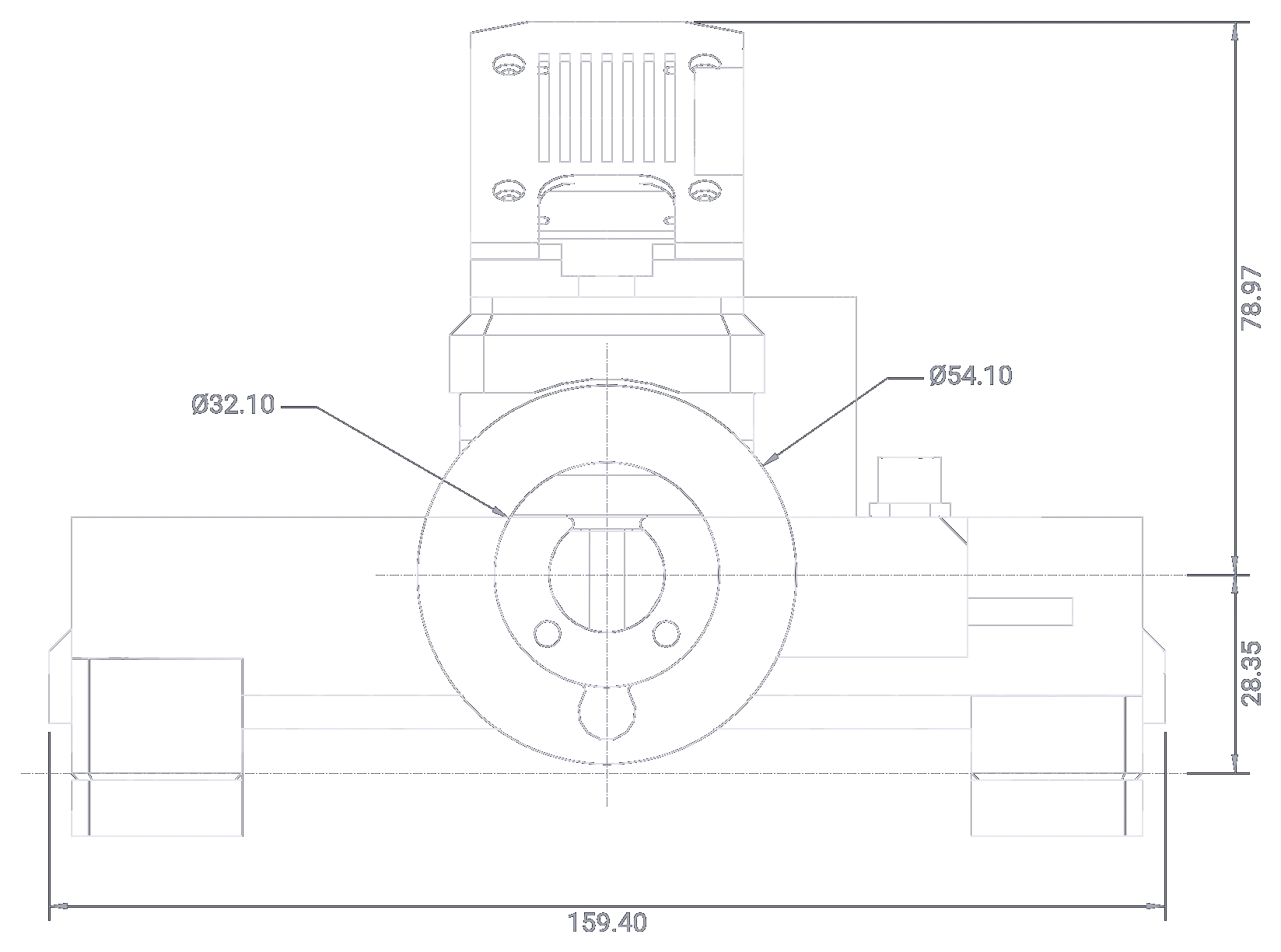
The drawings show the variant of the 3D model: the 150 mm rail, the 21.5 mm stepper and the solid jaws, with the jaws fully open. All dimensions are in millimetres, measured on the gripper's CAD as the robot model carries it. Heights are counted from the coupler's back face, the face that rests against the robot; the coupler axis is the gripper's axis on the robot.
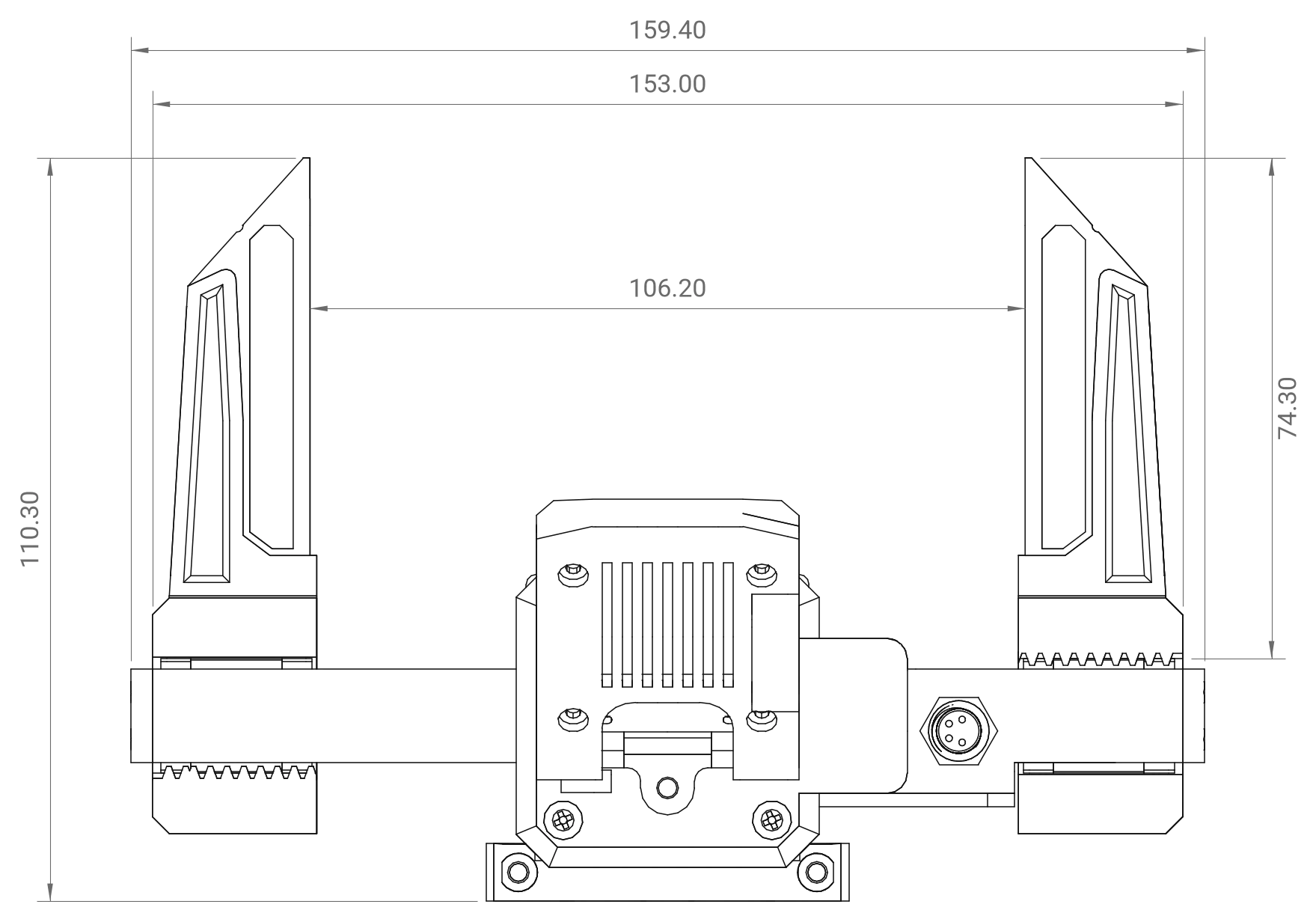
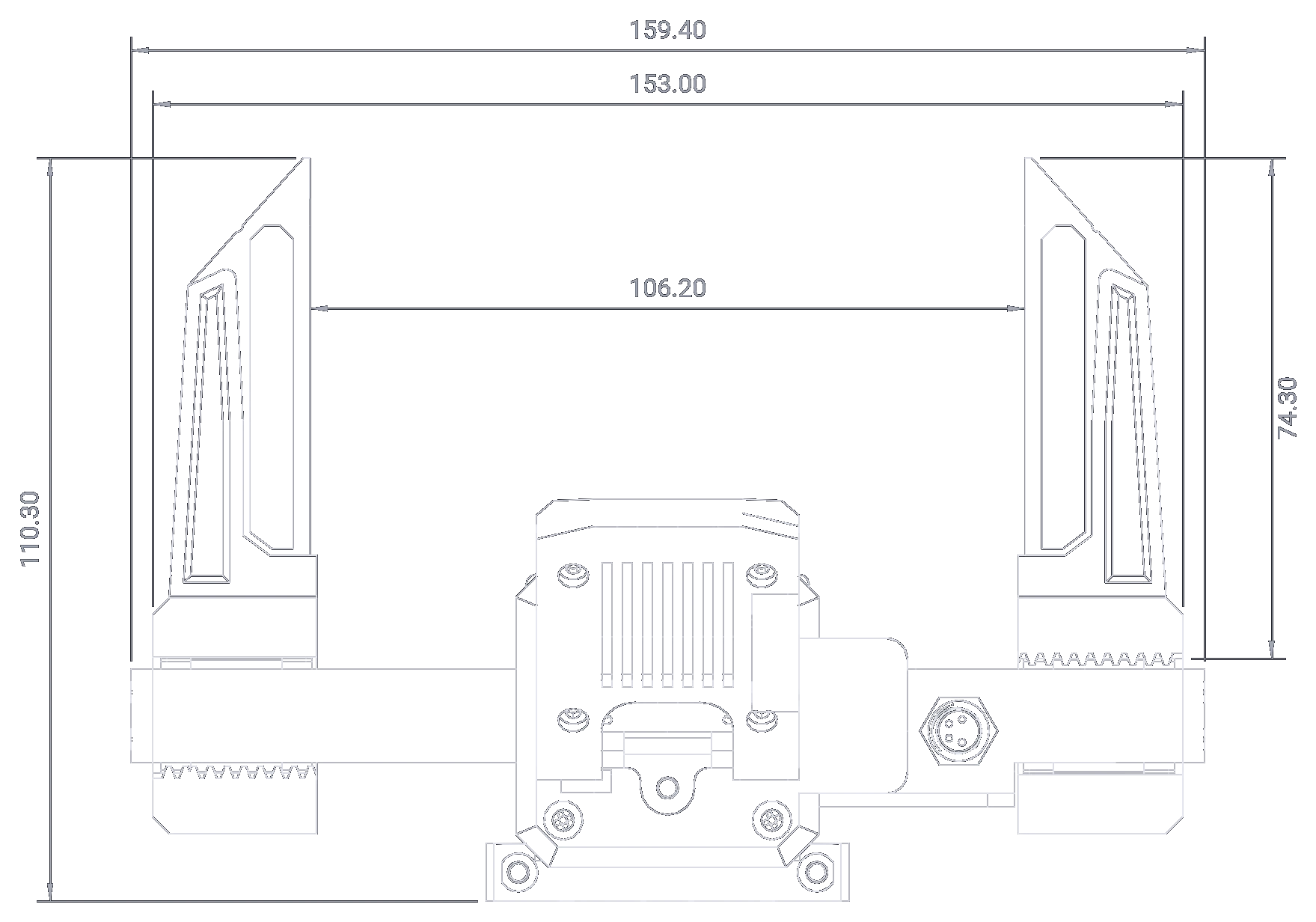
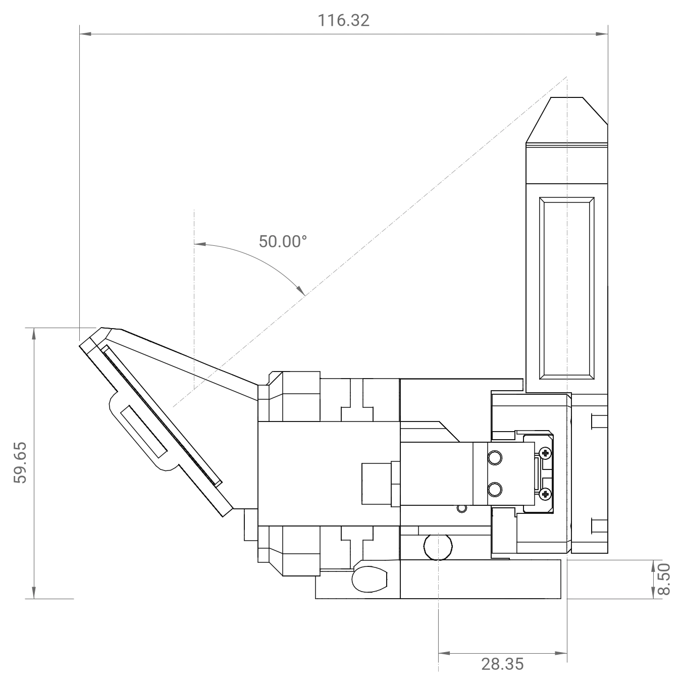
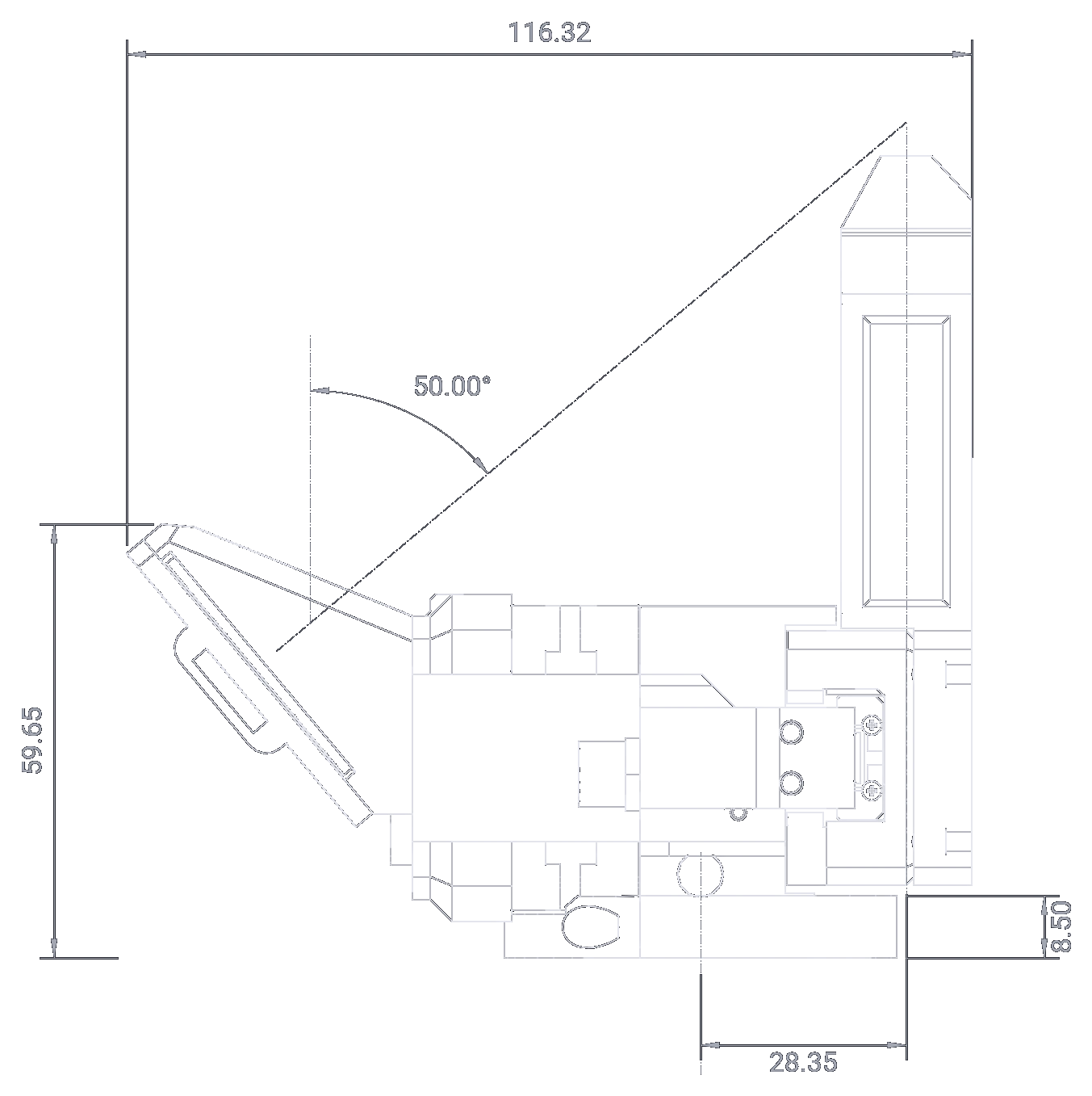
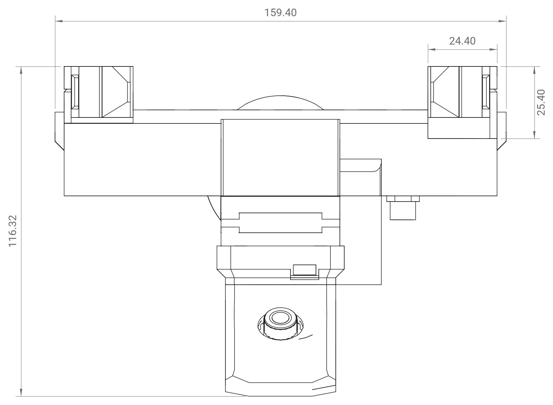
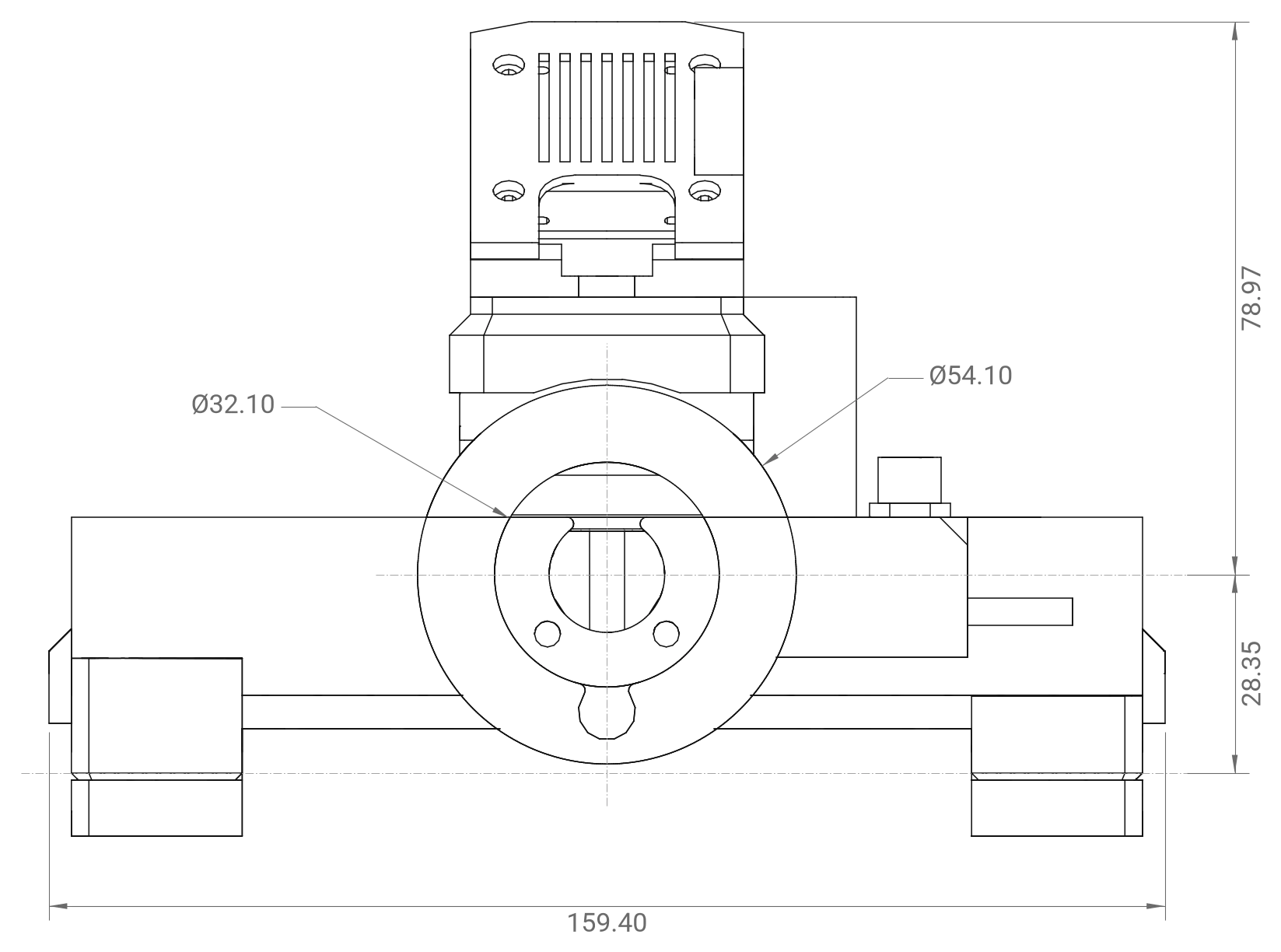
The recess is 6.50 mm deep; the flange of the shaft coupler sits in it. The PAROL6 ring cover has the same 54.10
and 32.10 mm circles (Mounting on a robot). tools/dimension_drawings.py in this site's
repository draws the four views from the model and prints every number on them.
Other rails and steppers
The rail sets the width and the stroke; the stepper sets how far the stepper cover, and the camera mount on top of it, stand away from the rail. Neither changes the coupler, the jaws or the 110.30 mm to the jaw tips. The lengths below are measured in the parts' STEP files; the overall sizes add them to the drawn variant.
| Rail | Stroke | Body | Over the jaw blockers | Printed parts |
|---|---|---|---|---|
| 100 mm | 55 mm | 103.00 mm | 109.40 mm | MSG_Gripper_body_100mm, gripper_jaw_100mm_L/R |
| 150 mm (drawn) | 105 mm | 153.00 mm | 159.40 mm | MSG_Gripper_body_150mm, gripper_jaw_150mm_L/R |
| 200 mm | 155 mm | 203.00 mm | 209.40 mm | MSG_Gripper_body_200mm, gripper_jaw_200mm_L/R |
The jaw blockers at the two ends of the rail are 3.20 mm thick each. On the drawn 150 mm rail the open jaws stand flush with the ends of the body (153.00 mm over the jaws).
| Stepper | Motor | Stepper cover | Cover's outer end, from the 21.5 mm one | Jaws to the top of the camera mount | Coupler axis to the top of the camera mount |
|---|---|---|---|---|---|
| 21.5 mm (drawn) | 17HS08-1004S | 34.40 mm | 0 | 116.32 mm | 78.97 mm |
| 40 mm | 17HS16-2004S1 | 51.40 mm | +18.50 mm | 134.82 mm | 97.47 mm |
| 60 mm | 17HS24-2104S | 71.40 mm | +38.50 mm | 154.82 mm | 117.47 mm |
CAD
The STEP files of every part are in the product repository, and are the reference for anything that has to fit:
- STEP files:
Common parts(the ring covers, the camera mount and its lid, the connector lid, the jaw blocker, the stepper spacer),Linear rail dependant parts(the body and the jaw carriers per rail length),Stepper dependant parts(the covers and spacers per stepper length),Gripper jaws attachment(the jaw designs),Tools(the magnet tool). There is no STEP file of the whole gripper; the robot model below is the assembled gripper. - Print files: the same parts as 3MF, ready to slice.
For simulation
The product repository's msg_description guide links the gripper's models, which are kept in robot_descriptions: standalone URDF and MJCF (MuJoCo) packages of the gripper with solid or soft TPU jaws, with their meshes, collision shapes and mass properties, and the PAROL6 and PAR6 models with the gripper mounted. The numbers a robot needs, the tool centre point, the mass and the inertia, are on Data for robot integration.
CAD and downloads lists everything that can be downloaded.
Comments
Found a mistake on this page? Edit it on GitHub · Report it · Get help · This page as Markdown · llms.txt · The whole manual as PDF