The serial terminal
Motor GUI is the usual way to work with the driver; a plain serial terminal is the alternative, and it is what
the console inside Motor GUI is. Everything in this manual that is done in the GUI is also one # command, and
the terminal shows the driver's answers exactly as it prints them, which is useful when something does not work.
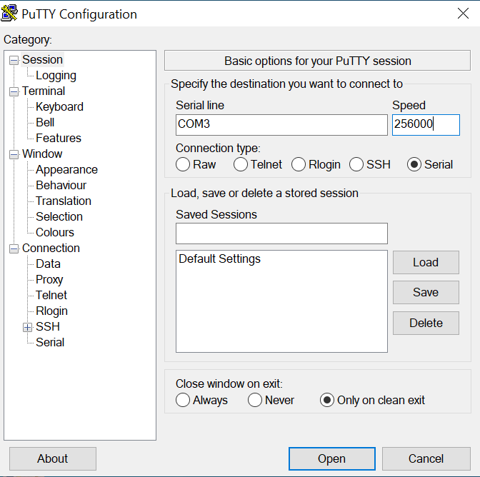
The driver talks on its UART connector at 256000 baud, 8N1, 3.3 V. Any terminal that sends a line ending in CR+LF works.
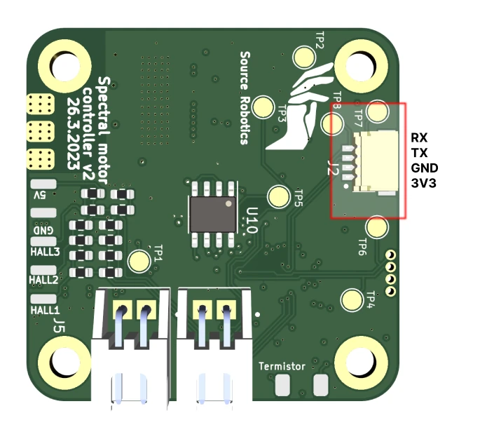
Connecting
- Plug the USB-to-serial adapter into the UART connector with the UART cable. With another adapter: 3.3 V only, and cross TX and RX: the driver's TX to the adapter's RX, the driver's RX to the adapter's TX.
- Connect the motor supply. The adapter's 3.3 V powers the driver's logic, so the driver answers over UART with only the adapter plugged in, but it reports a Vbus error and refuses calibration and every motion command until the 12 to 29 V supply is on.
- Find the adapter's port:
The adapter is COM and a number. Device Manager lists it under Ports (COM & LPT): the entry that
disappears when you unplug the adapter is yours. An adapter that shows a warning sign there instead needs the
driver of its USB chip (on most 3.3 V adapters a CP210x or a CH340) from the chip maker.
The serial adapter is /dev/ttyUSB0 on most adapters, the CANvas adapter /dev/ttyACM0;
ls /dev/ttyUSB* /dev/ttyACM* lists them. To open them without root, join the dialout group once, then
log out and in again:
The serial adapter is /dev/cu.usbserial- and a few characters on most adapters, the CANvas adapter
/dev/cu.usbmodem and a number; ls /dev/cu.* lists them. Use the cu. name, not the tty. one, in a
terminal or a script.
Danger
5 V on the UART pins destroys the board.
A terminal
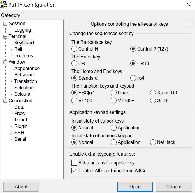
PuTTY needs to send CR+LF when you press Enter, which the stock build cannot. Use the modified PuTTY: under Terminal → Keyboard select the CR LF option, then open the serial port at 256000.
| Keyboard setting | Session |
|---|---|
 |
 |
With the firmware project
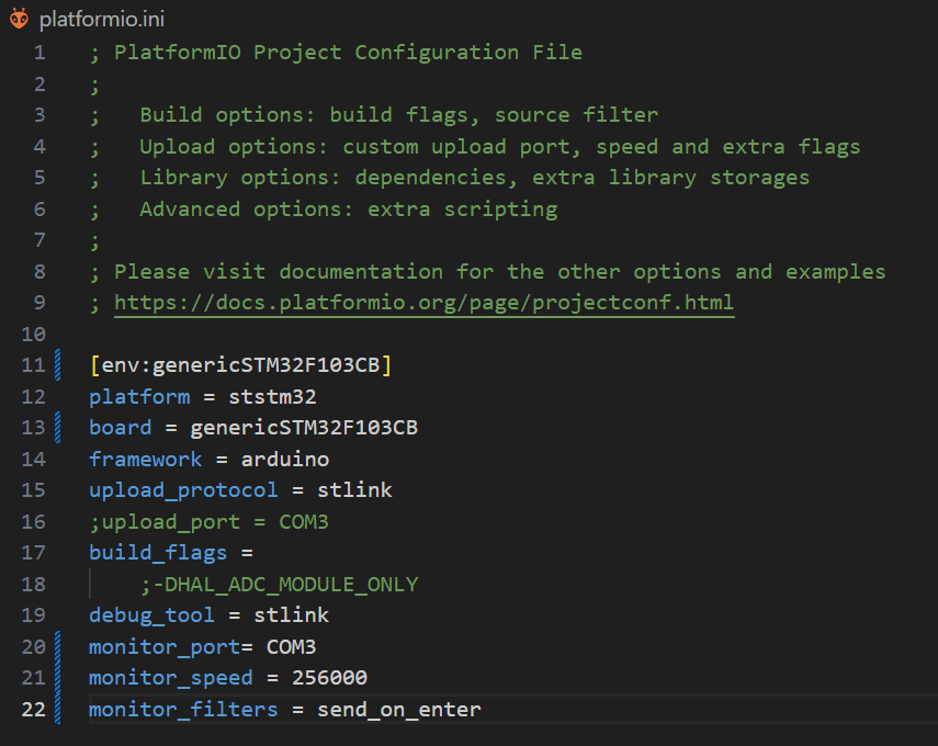
open in VS Code with the PlatformIO extension, the serial monitor (the plug icon in the status bar) uses the
speed and the send_on_enter filter from platformio.ini, so a line goes out with CR+LF when you press
Enter.
| platformio.ini | The monitor |
|---|---|
 |
 |
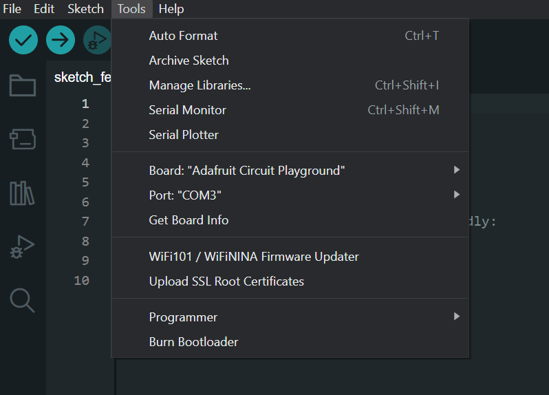
Select the adapter's port under Tools, any board (the monitor does not care), open the serial monitor, set 256000 baud and Both NL & CR as the line ending.
The first commands
prints the driver's identity: the hardware and firmware version, the CAN ID, the calibration state and the motor
parameters. #Help (firmware 106 and newer) prints a short command reference, #Error the active errors,
#SERNUM the serial number and #Param the gains.
Check
#Info answers with the driver's identity, the hardware and firmware version first. If nothing comes back:
the baud rate, the CR+LF line ending, TX and RX, see
The driver does not answer.
Every command starts with #, and a Set/Get command takes one number after a space: #P 16384 moves to position
16384; #P alone prints the position. Names are case-sensitive. The whole set is in the
UART commands reference, and Over UART explains the
protocol.
Comments
Found a mistake on this page? Edit it on GitHub · Report it · Get help · This page as Markdown · llms.txt · The whole manual as PDF