Wiring the stepper
A bipolar stepper has two coils and four wires. One coil goes to the terminals A+ and A−, the other to B+ and B−. Which coil is A and which is B does not matter, and neither does the polarity of each coil: firmware 105 and newer finds the wiring during calibration and compensates it.
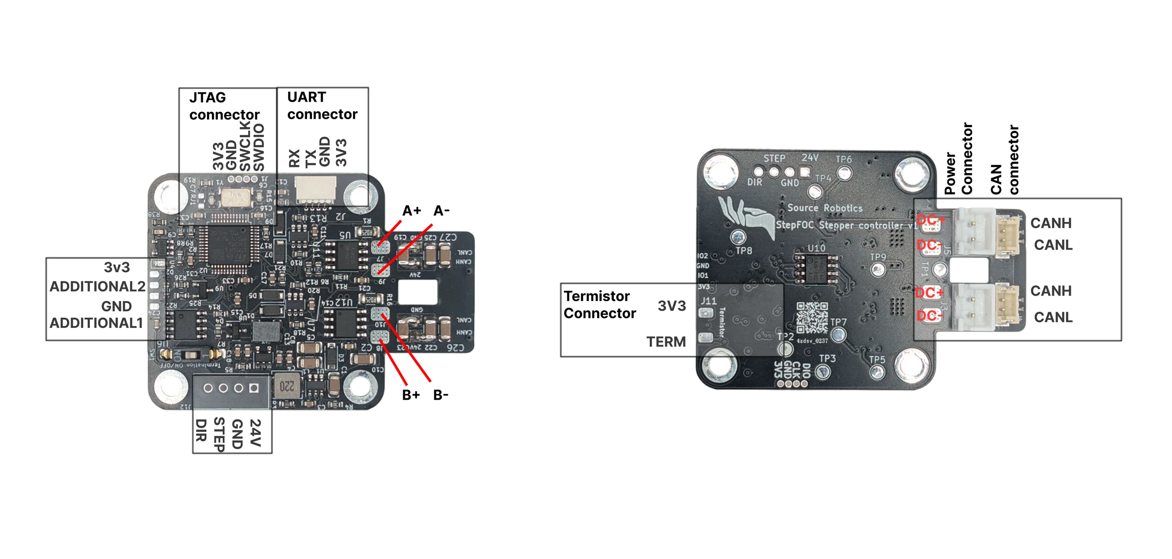
Finding the two coils
On most stepper motors the colours give the pairs away: black and green are one coil, red and blue the other. The Stepperonline motors of Tested motors are wired that way: black to A+, green to A−, red to B+, blue to B−.
| Coil | Usual wire colours | Terminals |
|---|---|---|
| A | black, green | A+, A− |
| B | red, blue | B+, B− |
Not every maker follows it, so check with a multimeter on the resistance range: the two wires of one coil show the coil's resistance, a few ohms; two wires of different coils show no connection. Most datasheets also name the pairs (A/C and B/D, or the colours).
Soldering
- Cut the leads to a comfortable length: long enough to reach the pads with the board mounted, short enough not to get into the motor's shaft. If your firmware is older than 105 (see Releases and versions), leave them long enough to swap one pair later.
- Tin the leads and solder them to the pads: one coil to A+ and A−, the other to B+ and B−.
- Make sure no strand bridges two pads and that nothing touches the motor housing.
Warning
Never connect or disconnect the motor while the driver is powered.
Phase order and direction
Calibration spins the motor in open loop and watches the encoder. With firmware 105 and newer, a reversed coil is
detected and compensated in software (the firmware applies a reflection of the current frame, which is what a
physical swap would do), so the motor calibrates identically with any wiring, and positive commands turn the motor
counter-clockwise seen from the magnet side. With firmware 103, a reversed coil fails the open-loop step with
Open loop: Failed / Switch motor phases and try again!; swap A+ and A− and calibrate again.
Because calibration compensates the wiring, the positive direction is tied to the encoder: with firmware 105 and
newer, swapping the wires of a coil and calibrating again does not change it. The firmware has no setting that
reverses it (#Dir is stored but not used). If you want the other direction to be positive, negate the setpoints
and the position, speed and current you read back in your host program.
Comments
Found a mistake on this page? Edit it on GitHub · Report it · Get help · This page as Markdown · llms.txt · The whole manual as PDF