The driver at a glance
STEPFOC is a field-oriented controller for bipolar stepper motors. It sits on the back of a NEMA 17 motor, reads the rotor position from a magnet on the motor shaft, and drives the two coils with sinusoidal currents the way a servo drive does, instead of the fixed step currents of a conventional stepper driver. The result is a stepper that runs quietly and efficiently, never loses steps, reports its position, and can be commanded in position, speed, current (torque) or impedance.
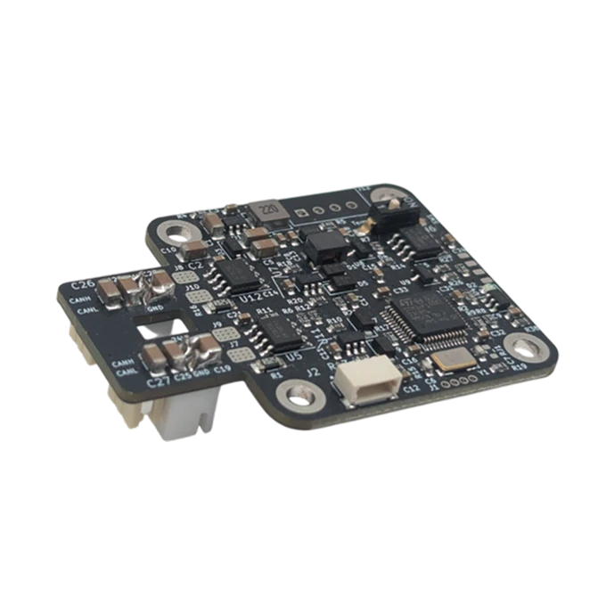
What is on the board
| Part | What it does |
|---|---|
| STM32F103CB microcontroller | runs the control loops at 6250 Hz and the CAN and UART interfaces |
| 14-bit magnetic encoder (MT6816) | reads the position of the magnet on the motor shaft: 16384 ticks per revolution |
| H-bridge driver with inline current sensing | drives the two coils with up to 2.8 A and measures the phase currents |
| 16 Kbit EEPROM | keeps the configuration and the calibration over a power cycle |
| Two CAN connectors and two power connectors | daisy-chain several drivers on one bus and one supply |
| CAN termination switch | the 120 Ω resistor the first and the last node need |
| UART connector (3.3 V) | the serial terminal: every setting, calibration, tuning |
| Thermistor connector | an NTC on the motor for temperature protection |
| ADDITIONAL2 pin | an input or output you can use: HALL mode homes against a sensor wired here |
| JTAG pads (1.27 mm) | the programming adapter, for installing the bootloader or for development |
| Status LED | normal operation, calibration or error, see below |
The connectors and their pinout are in Connectors and pinout.
What the firmware does
The firmware closes three nested loops on the motor: a current (torque) loop, a velocity loop around it and a position loop around that, plus an impedance (PD) loop that makes the motor behave like a spring and damper. A command picks the loop: a current setpoint, a speed, a position or a PD setpoint. Open-loop stepping, a voltage-torque mode and a homing mode against a sensor exist beside them; Control modes describes each.
The driver protects itself and the motor: it stops on a supply voltage outside the limits, on an encoder fault (no
magnet), on a motor over-temperature (with the thermistor), on an E-stop command and on a watchdog that runs out.
The status LED and #Error tell which; see Errors and recovery. It does not monitor
its driver stage: a fault there is not reported.
How it is controlled
- UART, a 3.3 V serial port at 256000 baud: human-readable commands such as
#P 16384, and the only way to run the calibration. See Over UART. - CAN, 1 Mbit/s, up to 14 drivers on one bus (node IDs 0 to 13): compact frames for real-time control from a PC with the CANvas adapter, a microcontroller or a robot control box. See Over CAN.
- Python, the
Spectral-BLDClibrary on top of CAN. See With Python. - Motor GUI, in the browser, over serial or CAN: the usual tool for setup, testing and tuning. See Motor GUI.
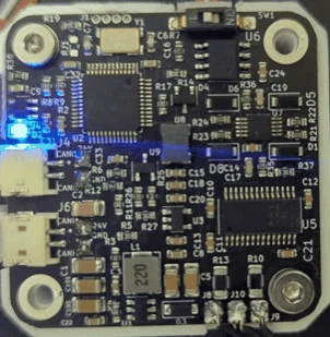
The status LED
| Pattern | Meaning |
|---|---|
| three short flashes and a pause | normal operation: no error, calibrated |
| fast flashing, about ten times a second | the calibration routine is running |
| on, not flashing | error mode: at least one error is active, or the motor is not calibrated |
The LED can be turned off with #LED 0.
| Normal operation | Calibration | Error mode |
|---|---|---|
 |
 |
 |
Comments
Found a mistake on this page? Edit it on GitHub · Report it · Get help · This page as Markdown · llms.txt · The whole manual as PDF