Motor GUI
Motor GUI is the usual way to set up, test and tune a driver: a tool in the browser that connects to one driver over the serial adapter or to a bus of drivers over the CANvas adapter, shows the state, moves the motor, runs the calibration, tunes the loops with live plots, records telemetry and updates the firmware. Nothing is installed. Everything it does, the driver also does from a terminal or from Python — the GUI reads and writes the same settings — so every procedure in this manual shows the GUI first and the terminal command beside it.
The browser
Motor GUI reaches the hardware through the browser's serial port access (Web Serial), which Chromium-based browsers have: Chrome, Edge, Brave, Opera. Firefox and Safari cannot open serial ports.
Two ways to connect
| Adapter | Use it for | |
|---|---|---|
| One driver over serial | the 3.3 V USB-to-serial adapter on the driver's UART connector, 256000 baud | the first setup and calibration (calibration runs over UART only), tuning on the bench |
| A bus over CAN | the CANvas adapter; it appears as a serial port and speaks slcan | every driver on the bus by its node ID: testing a machine, updating firmware on all joints |
Opening the port
- Plug in the adapter and the motor supply. The adapter alone powers the driver's logic, enough to open the port and read the settings, but the driver reports a Vbus error and will not calibrate or move until the supply is on.
- Open motorgui.com, choose the connection kind, and Connect. The browser asks which port; pick the adapter's.
- The driver's identity appears: hardware version, firmware version, serial number, batch date, whether it is
calibrated and activated, and the active errors: what
#Info,#SERNUMand#Errorprint in a terminal.
If the port is not offered, the browser is not Chromium-based, or another program holds the port (a terminal left open, PlatformIO's monitor), or the operating system does not give the browser the port:
The adapter is COM and a number. Device Manager lists it under Ports (COM & LPT): the entry that
disappears when you unplug the adapter is yours. An adapter that shows a warning sign there instead needs the
driver of its USB chip (on most 3.3 V adapters a CP210x or a CH340) from the chip maker.
The serial adapter is /dev/ttyUSB0 on most adapters, the CANvas adapter /dev/ttyACM0;
ls /dev/ttyUSB* /dev/ttyACM* lists them. To open them without root, join the dialout group once, then
log out and in again:
The serial adapter is /dev/cu.usbserial- and a few characters on most adapters, the CANvas adapter
/dev/cu.usbmodem and a number; ls /dev/cu.* lists them. Use the cu. name, not the tty. one, in a
terminal or a script.
The browser's port picker lists the same adapters. If the port opens and nothing appears: the driver is unpowered, or TX and RX are crossed on an adapter that is not the Source Robotics one.
What is on the screen
- State: the identity above, the control mode the driver is in, the errors, and Clear errors.
- Jog: Jog position, Jog velocity and Jog current move the motor in the matching control mode; Send setpoint sends a value in the current mode. Live stream while dragging follows a slider as you move it.
- Plots of position, speed and current, panning and zooming, with the value under the pointer.
- Settings: the motor parameters (pole pairs, resistance, inductance), the limits (current, velocity, voltage), the loop gains with Apply gains and Apply preset, the CAN node ID, the watchdog, the thermistor. The GUI marks Unsaved changes until you Save to the driver's EEPROM; Default restores the factory values.
- Calibration: starts
#Caland shows the driver's log step by step; afterwards the phase order and direction, Kt, KV and the flux linkage it found. - Telemetry: the stream from the driver, and recordings of it for a test or a bug report.
- Firmware update: the releases from GitHub, flashed through the bootloader; Scan bootloaders on a bus.
- Gripper: the gripper controls, for a driver in gripper mode.
- Console: type any
#command by hand; the answer appears below it. - Wiring diagrams and Keyboard shortcuts under help.
Screen guide
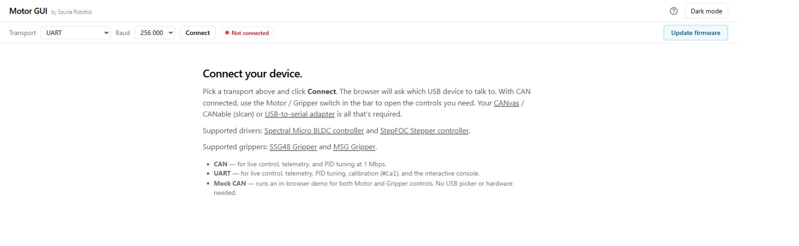
Figure 5.1: 1. Transport: choose UART for the serial adapter. 2. Baud: 256000 for a stock driver. 3. Connect: choose the adapter in the browser's port picker.
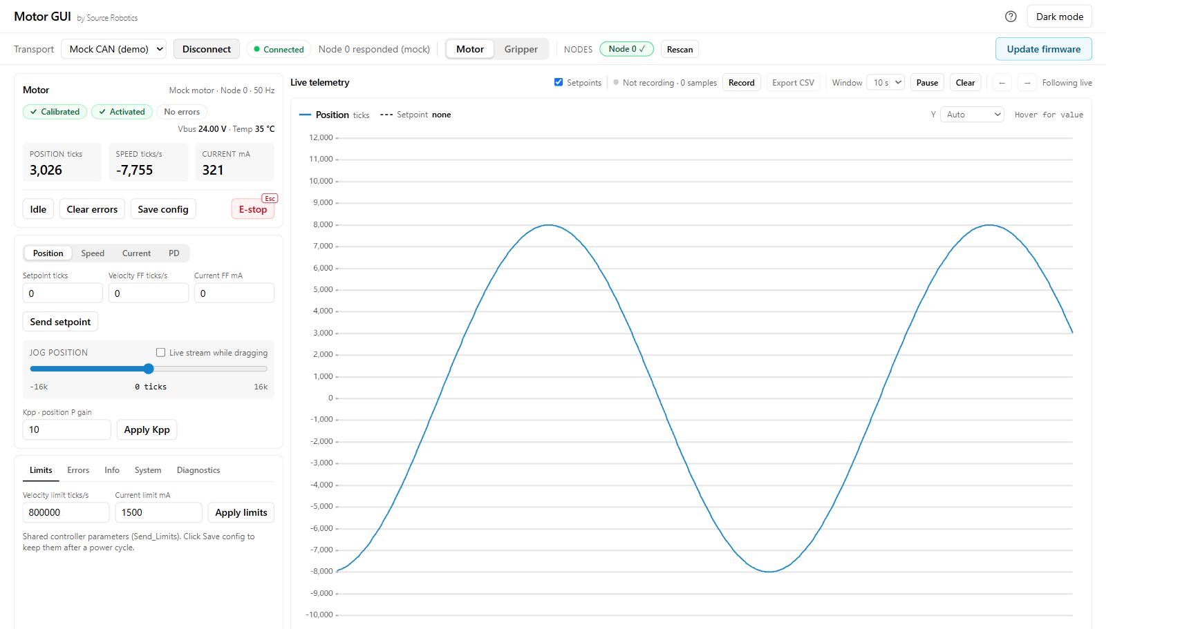
Figure 5.2: 1. Connection and node: confirm the intended driver. 2. State: calibration, activation and faults. 3. Command mode: setpoints and jog controls. 4. Live telemetry: measured position, speed and current. This screenshot uses Mock CAN (demo), not physical hardware.
Check
After connecting real hardware, the state and identity belong to your driver. If they do not appear, check the transport, the selected port, the supply and the TX/RX wiring before trying to move.
Try it without hardware
Open Motor GUI, choose Mock CAN (demo), and press Connect. The motor and gripper panels run in the browser without a port picker. Motor calibration (#Cal) still requires a real UART connection; the CAN demo does not perform it.
What next
Motor parameters and calibration is the first thing to do with a connected driver; Working in Motor GUI covers everyday use: moving the motor, the plots, recordings, several motors on a bus.
Comments
Found a mistake on this page? Edit it on GitHub · Report it · Get help · This page as Markdown · llms.txt · The whole manual as PDF