Working in Motor GUI
Everyday use of the driver from Motor GUI: moving the motor, watching it, recording what it does, running several motors, and the few things that only work from the console.
Moving the motor
The jog controls send setpoints in the matching control mode: Jog velocity turns the motor at a speed in encoder ticks per second (16384 is one revolution per second), Jog position moves it to a position in ticks, Jog current applies a torque in mA. Send setpoint sends a value in the mode the driver is in. Idle stops the motor; Control modes says what each mode does. With Live stream while dragging the setpoint follows the slider, which is the quickest way to feel a tuning change.
Watching it
The plots show position, speed and current as the driver reports them. Pan and zoom to a move; hover for the value. A step in the position setpoint shows overshoot and settling at once, a speed step shows the velocity loop's response; Current limit and loop tuning uses them step by step.
Recording
A recording keeps the telemetry stream to a file: New recording, run the move, Stop recording. Record the response before and after a tuning change to compare them, or a failure to attach to a bug report (Report a problem).
Clearing errors
The errors the driver reports are listed with the state; Clear errors sends what #Clear does. An error whose
cause is still present comes straight back; Errors and recovery says what each one needs.
Several motors
Over the CANvas adapter the GUI sees every driver on the bus and addresses each by its node ID. Give each driver its own ID over the serial adapter first (the CAN node ID in the settings, then Save), terminate the first and the last node, and set a watchdog (Watchdog ms) on a bus that drives something that must not run away: Power and the CAN daisy chain, Over CAN.
Gripper
A driver in gripper mode shows the gripper controls: calibrate the jaws, a position from open to closed, a speed, a current limit, and the state the gripper reports. No gripper connection means the driver is not in gripper mode or not on the bus. Gripper mode.
Firmware updates
Firmware update lists the releases from GitHub and flashes one through the bootloader; on a bus, Scan bootloaders finds the boards. Updating through the bootloader.
The console
Anything the GUI has no control for is one # command away in the console, with the driver's answer below it;
the whole set is in the UART commands reference. The cyclic output (#Cyc) is what
the GUI's telemetry stream uses over serial, so do not start it by hand while the plots run.
Reading a fault
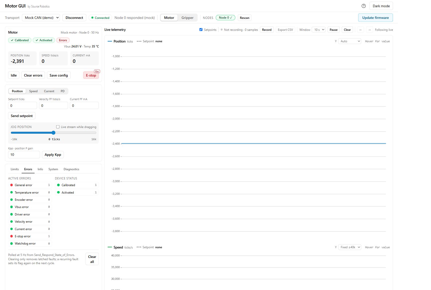
Figure 6.3: 1. Errors state: a fault is active. 2. Errors tab: inspect individual flags. 3. E-stop error: 1 identifies the latched fault in this simulation. 4. Clear errors: clear it after removing its cause; a persistent cause returns on the next update. Screenshot captured from Mock CAN (demo).
Check
After recovery the fault flag returns to 0 and the state shows No errors. If it returns, stop and follow Errors and recovery.
Comments
Found a mistake on this page? Edit it on GitHub · Report it · Get help · This page as Markdown · llms.txt · The whole manual as PDF