Mounting on a robot
The gripper mounts by its coupler connector, the round part on the back of the body. The repository has three, for PAROL6, PAR6 and the UR5 flange, and a STEP template for your own.
| Robot | Part | Where |
|---|---|---|
| PAROL6 | coupler_connector_PAROL6.STL |
Gripper STL parts |
| PAR6 | coupler_connector_PAR6.STL |
the same folder |
| UR5 | UR_coupler_gripper.STEP |
STEPS/UR5 adapter plate |
| your own | coupler_connector_generic_STEP.STEP, the template |
STEPS |
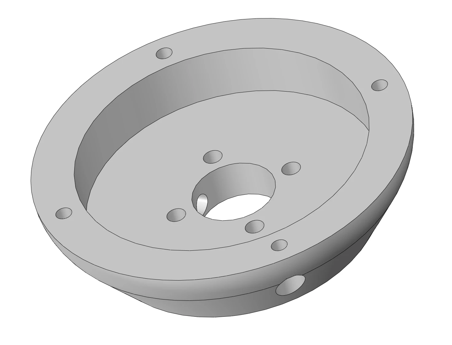
PAROL6
The PAROL6 coupler connector carries a shaft coupler with an 8 mm bore and two M4 clamp screws for the robot's last joint, and the homing tab that joint 5 homes against.
- Fit
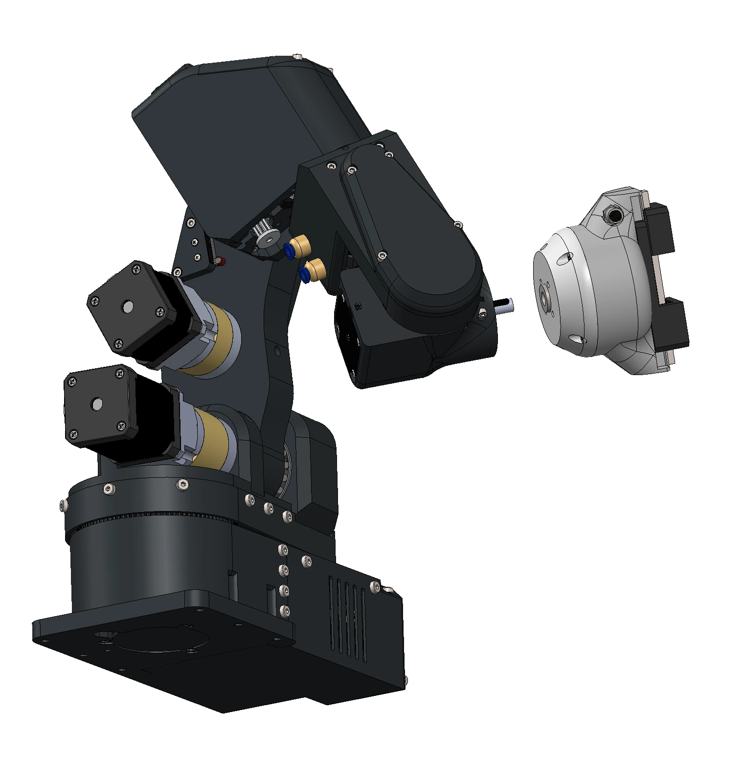
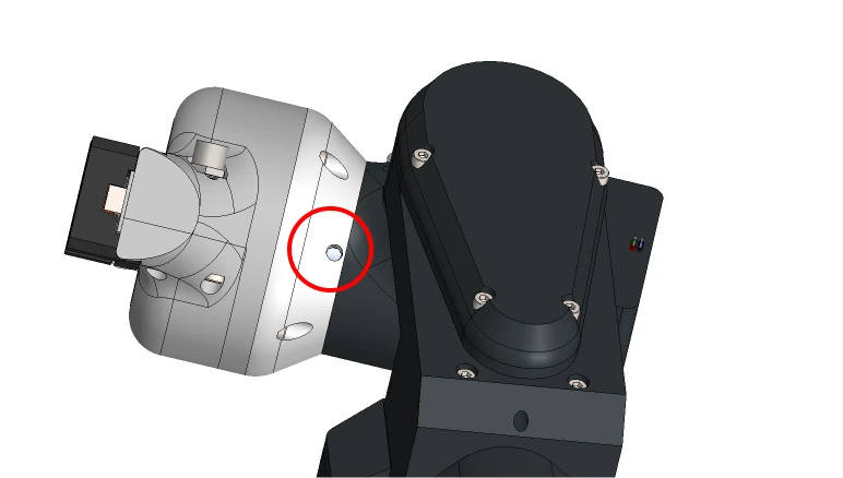
coupler_connector_PAROL6to the gripper, with the homing tab on the same side as the gripper's cable connector and an M3 × 12 screw in the marked hole, as the last pages of the assembly manual show. - Slide the gripper onto the J6 motor shaft.
- Tighten the two screws of the shaft coupler, one on each side, with blue threadlocker.
- Connect the PAROL6 gripper cable to the gripper and to the robot's gripper port (The cable).
The PAROL6 software needs to know the gripper is there, and the control board firmware needs the joint 5 homing offset for it: On PAROL6 and PAR6.
PAR6
coupler_connector_PAR6 bolts to the PAR6 wrist; the PAR6 gripper cable, wired differently from the PAROL6 one,
goes to the robot's tool connector.
Another robot
Adapt the template to your flange, or use the UR5 adapter plate as a starting point. Keep the gripper's connector reachable, and route the cable so that it cannot be pulled by the robot's motion.
On the bench
For testing, clamp the body, not the jaw plates or the rail, and leave the whole stroke free: calibration moves the jaws from one end stop to the other without any command from you.
Comments
Found a mistake on this page? Edit it on GitHub · Report it · Get help · This page as Markdown · llms.txt · The whole manual as PDF