The cable
One cable with an M8 4-pin connector powers the gripper and carries its CAN bus. The robot end differs from robot to robot.
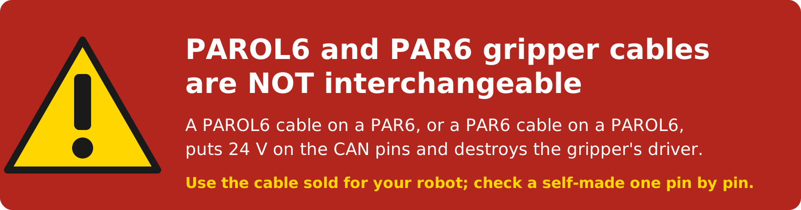
PAROL6 and PAR6 cables are different
The two robots put the four signals on different pins of their gripper port. The PAROL6 cable in a PAR6, or the other way round, puts 24 V on the CAN bus and destroys the gripper's driver. Use the cable sold for your robot, and check a self-made cable pin by pin.
The cables from the shop
| Robot | Cable |
|---|---|
| PAROL6 | PAROL6 gripper cable |
| PAR6 | the PAR6 gripper cable, coming to the shop |
Making your own
For a bench setup, another robot, or a replacement, the cable is four wires between an M8 4-pin female connector at the gripper and whatever the other end needs:
| Part | Quantity | BOM |
|---|---|---|
| 26 AWG 4-wire twisted-pair cable, 0.15 mm², shielded | about 0.4 m | cable |
| M8 4-pin female cable connector (the gripper has the male) | 1 | connector |
| M8 4-pin male cable connector, for a robot with an M8 port | 1 | the same listing |
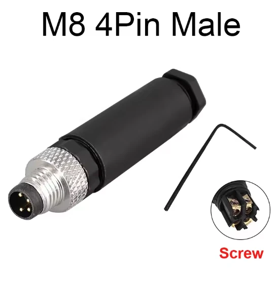
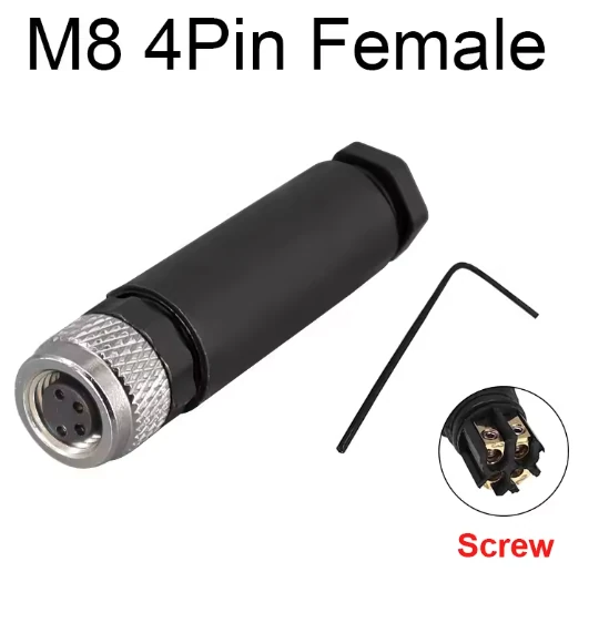
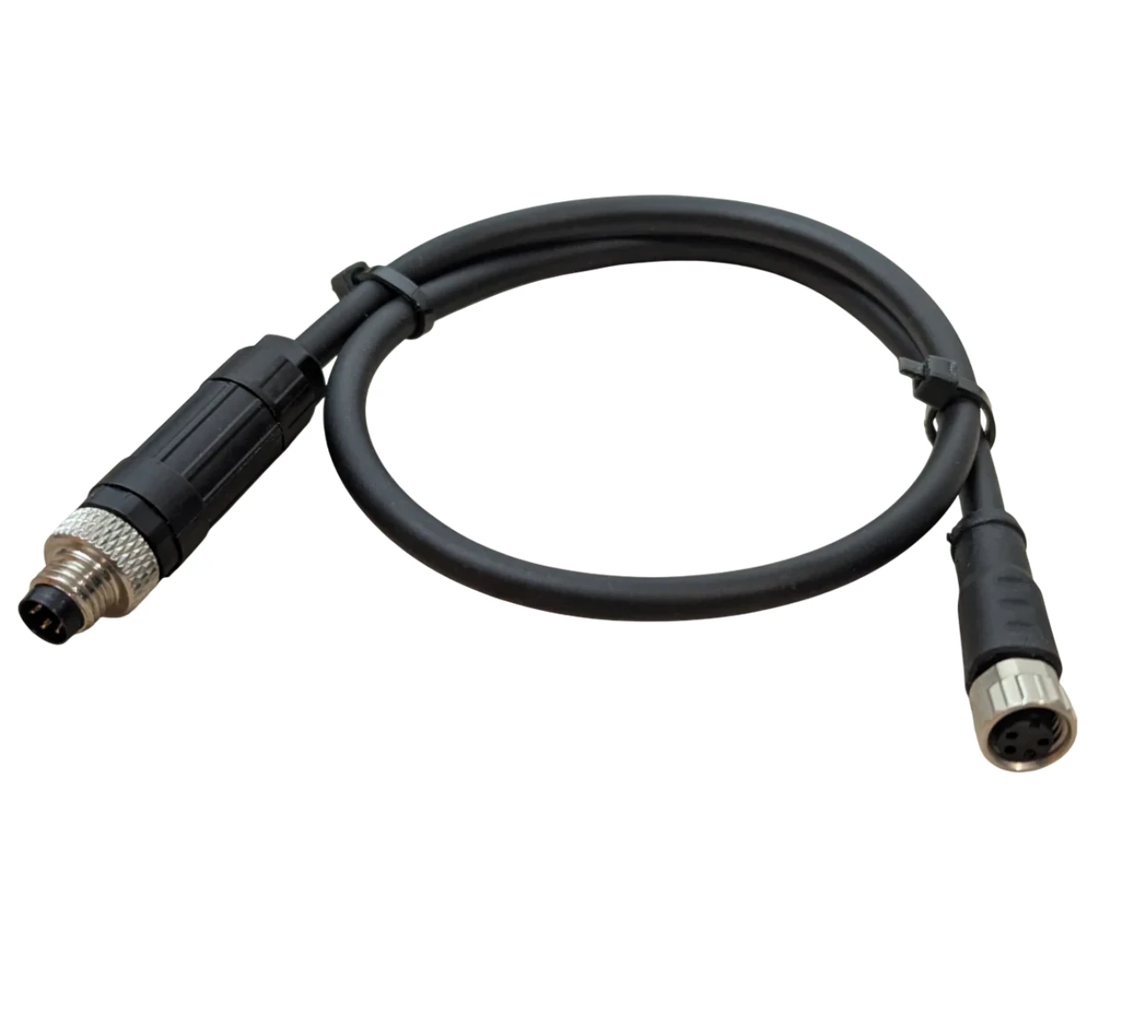
Wire it as the diagram for your robot shows. Pin 1 to 4 are the numbers moulded into the M8 connectors; the colours are those of the cable in the BOM.
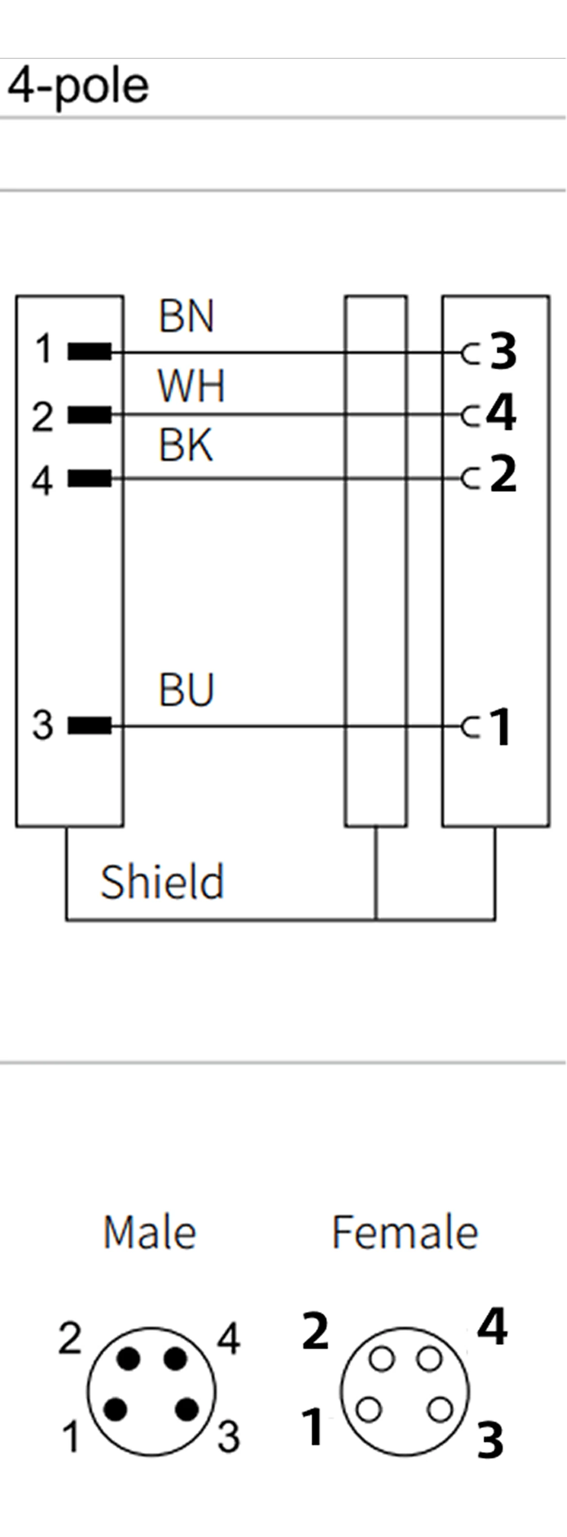
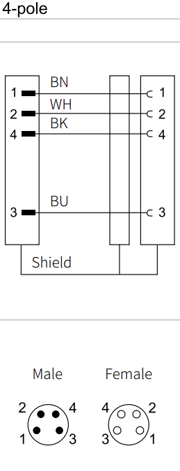
Connect the gripper's 24V and GND to a 24 V supply and its CANH and CANL to your CAN interface; on a PC that is the CANvas adapter's CAN terminals. Connector and pinout shows which pin of the gripper's connector is which signal. Twist the CAN pair, keep the cable short at 1 Mbit/s, and terminate the bus at both ends (CAN termination).
Connect the shield at one end only. Check continuity and the absence of shorts between all four pins before the first power-up.
Handling
Plug and unplug with the supply off. Route the cable along the robot with enough slack for the wrist's full motion, and keep it away from the jaws' travel.
Comments
Found a mistake on this page? Edit it on GitHub · Report it · Get help · This page as Markdown · llms.txt · The whole manual as PDF