Control modes
The driver is always in one control mode. A command that carries a setpoint switches to the mode that uses it;
#Idle or Send_Idle switches back to idle. The driver refuses the closed-loop modes while it is not calibrated or
while an error is active.
stateDiagram-v2
    [*] --> NotCalibrated: power-up, no saved calibration
    [*] --> Idle: power-up, saved calibration
    NotCalibrated --> Calibration: #Cal
    Calibration --> Idle: success, #Save
    Calibration --> NotCalibrated: a test fails
    Idle --> ControlMode: a setpoint
    ControlMode --> Idle: #Idle, Send_Idle
    ControlMode --> Error: a fault
    Idle --> Error: a fault
    Error --> Idle: #Clear, cause gone
A setpoint is #P, #V, #Iq, #PD or a CAN motion frame, and a new setpoint switches the mode without
passing through idle; a fault is any of the errors on Errors and recovery.
| ControlMode | What the motor does | Entered by | Setpoint unit |
|---|---|---|---|
| Idle | nothing: coasts (phases open), or brakes (phases shorted) after #Brake 1 or Send_Settings; with an error it always coasts, see Braking in idle |
#Idle, Send_Idle, #Clear, errors |
— |
| Position | holds and moves to a position with the cascade of position, velocity and current loops | #P, Send_data_pack_1 (8 bytes) |
encoder ticks |
| Velocity | turns at a speed with the velocity and current loops | #V, Send_data_pack_1 (5 bytes) |
encoder ticks/s |
| Current (torque) | applies a current, so a torque, with the current loop alone | #Iq, Send_data_pack_1 (2 bytes) |
mA |
| PD (impedance) | behaves like a spring and a damper around a position, with KP and KD |
#PD, Send_data_pack_PD |
encoder ticks |
| Voltage torque | applies a voltage on the q axis directly, without the current loop | #Uq |
mV |
| Open loop | turns the stator field at a set electrical speed without the encoder in the loop; the rotor follows it like a stepper. It applies the voltage #Openv (5000 mV by default), not a current: #Ilim does not apply, and a low-resistance motor draws far more than its limit |
#Openloop |
electrical speed |
| Gripper | runs the gripper state machine: move to a jaw position with a speed and a current limit | #Grippos, Send_gripper_data_pack (with #Gripper 1) |
0 to 255 |
| Calibration | the calibration routine, or the gripper calibration | #Cal, #Gripcal |
— |
Braking in idle
#Brake 1 (or Send_Settings over CAN) makes the idle motor brake: the driver keeps the three phases shorted, so
the motor resists being turned. #Brake 0, the default, lets it coast. The setting is not saved: every power-up
starts with coasting. Braking works only in idle without an error; an error or an E-stop disables the driver, and
the motor coasts.
The braking current is not limited
A motor that is turned while it brakes drives its own back-EMF current through the shorted phases, and the current loop does not limit that current. Use braking only on a motor whose resistance keeps the current under the driver's 2.8 A at the speeds it turns at.
Units
- Position is in encoder ticks: 16384 per revolution of the motor shaft, counting up without limit over several revolutions. Positive is counter-clockwise seen from the encoder side of the board, see below.
- Speed is in encoder ticks per second: 16384 is one revolution per second, 60 rpm.
- Current is in mA. Torque is current times the motor's Kt, which calibration finds.
- Feedforward: the 8-byte motion frame carries a speed and a current feedforward beside the position, the 5-byte one a current feedforward beside the speed. They are added after the loops, so a host that knows the trajectory can command it directly and leave the loops to correct the rest. Send 0 when you do not use them.
Try it
As a position: 1.000 turns, 360.0° · as a speed: 60 rpm · the practical maximum for 11 pole pairs is about 2727 rpm
Torque: 0.30 Nm, 30 N·cm
The units of this page, with your numbers: 16384 encoder ticks per turn, the practical speed limit from the electrical frequency the control loop can follow (Ratings and limits), and the torque as Kt times the current.
Positive rotation
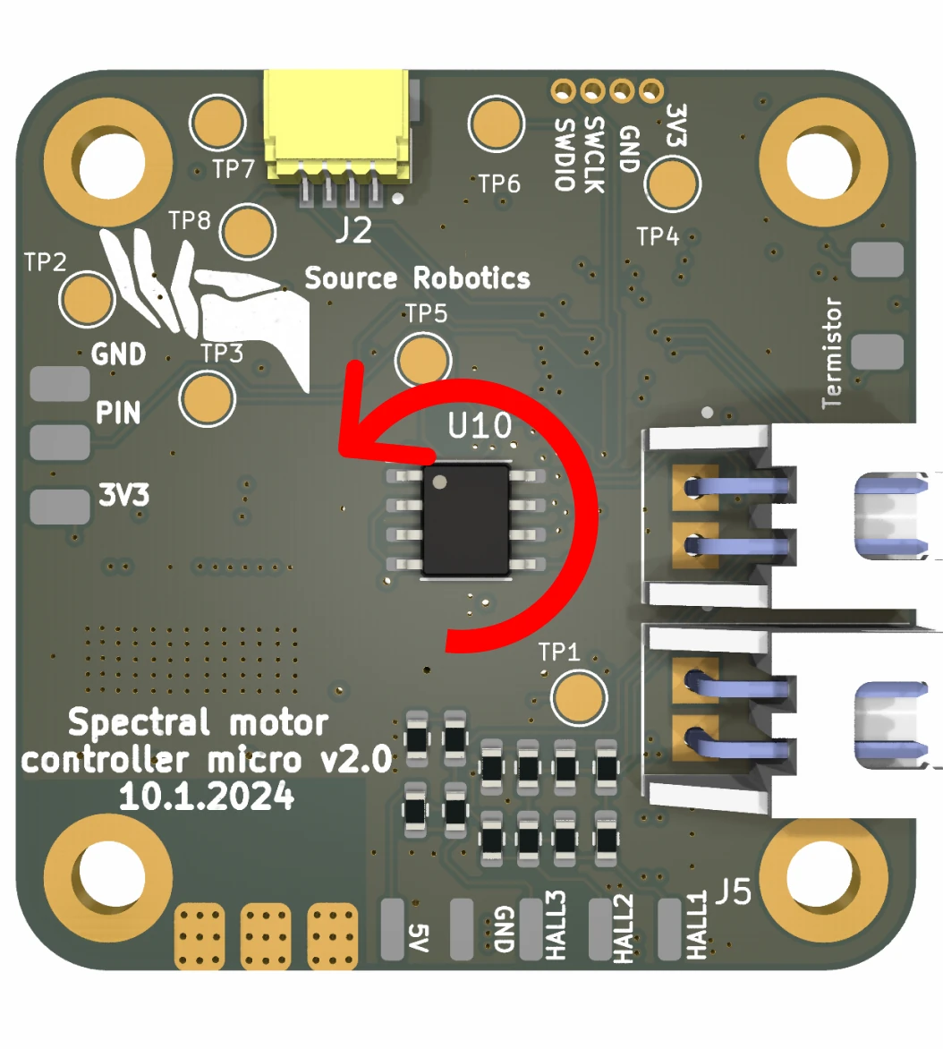
The direction is tied to the encoder, not to the wiring: since firmware 105 calibration compensates the order of the phases, so the motor turns the same way whichever wire went to which terminal.
Which mode am I in?
#Mode prints the mode: Idle mode, Position control, Speed control, Current control, PD control,
Open loop, Gripper mode or Gripper calib mode. In voltage-torque mode it prints nothing at all; #Uq then
prints the voltage setpoint.
Comments
Found a mistake on this page? Edit it on GitHub · Report it · Get help · This page as Markdown · llms.txt · The whole manual as PDF