Control modes
The driver is always in one control mode. A command that carries a setpoint switches to the mode that uses it;
#Idle or Send_Idle switches back to idle. The driver refuses every mode except idle, open loop included, while it
is not calibrated or while an error is active.
stateDiagram-v2
    [*] --> NotCalibrated: power-up, no saved calibration
    [*] --> Idle: power-up, saved calibration
    NotCalibrated --> Calibration: #Cal
    Calibration --> Idle: success, #Save
    Calibration --> NotCalibrated: a test fails
    Idle --> ControlMode: a setpoint
    ControlMode --> Idle: #Idle, Send_Idle
    ControlMode --> Error: a fault
    Idle --> Error: a fault
    Error --> Idle: #Clear, cause gone
A setpoint is #P, #V, #Iq, #PD or a CAN motion frame, and a new setpoint switches the mode without
passing through idle; a fault is any of the errors on Errors and recovery.
| ControlMode | What the motor does | Entered by | Setpoint unit |
|---|---|---|---|
| Idle | nothing: brakes (phases shorted), the default, or coasts (phases open), as set by #Brake / #Coast or Send_Settings; see Braking in idle |
#Idle, Send_Idle, #Clear, errors |
— |
| Position | holds and moves to a position with the cascade of position, velocity and current loops | #P, Send_data_pack_1 (8 bytes) |
encoder ticks |
| Velocity | turns at a speed with the velocity and current loops | #V, Send_data_pack_1 (5 bytes) |
encoder ticks/s |
| Current (torque) | applies a current, so a torque, with the current loop alone | #Iq, Send_data_pack_1 (2 bytes) |
mA |
| PD (impedance) | behaves like a spring and a damper around a position, with KP and KD |
#PD, Send_data_pack_PD |
encoder ticks |
| Voltage torque | applies a voltage on the q axis directly, without the current loop: clamped to #Vlim, not current-limited |
#Uq |
mV |
| Open loop | steps the motor like a plain stepper driver, without the encoder and without a current limit; see Open-loop stepping | #Openloop (continuous), #gosteps (a number of microsteps) |
electrical rad/s; microsteps |
| HALL | spins until a sensor on ADDITIONAL2 triggers, then holds the position reached; with a level trigger only while the pin stays at that level | #HALL, Send_data_pack_HALL |
encoder ticks/s |
| Gripper | runs the gripper state machine: move to a jaw position with a speed and a current limit | #Grippos, Send_gripper_data_pack (with #Gripper 1) |
0 to 255 |
| Calibration | the calibration routine, and the angle-offset step alone | #Cal, #Calangle, #Gripcal |
— |
Braking in idle
In idle the driver brakes: it keeps both coils shorted through the driver stage, so the motor resists being
turned. It does so at every power-up, and also with an error, which puts the driver in idle. #Coast (or
Send_Settings over CAN) lets the motor coast instead, with the coils open, until the next power-up: #Save does
not keep it. #Brake brakes again.
The braking current is not limited
A motor that is turned while it brakes drives its own back-EMF current through the shorted coils, and the
current loop does not limit that current. Do not let a load drive a braking motor fast; send #Coast first
when the shaft must turn freely.
Units
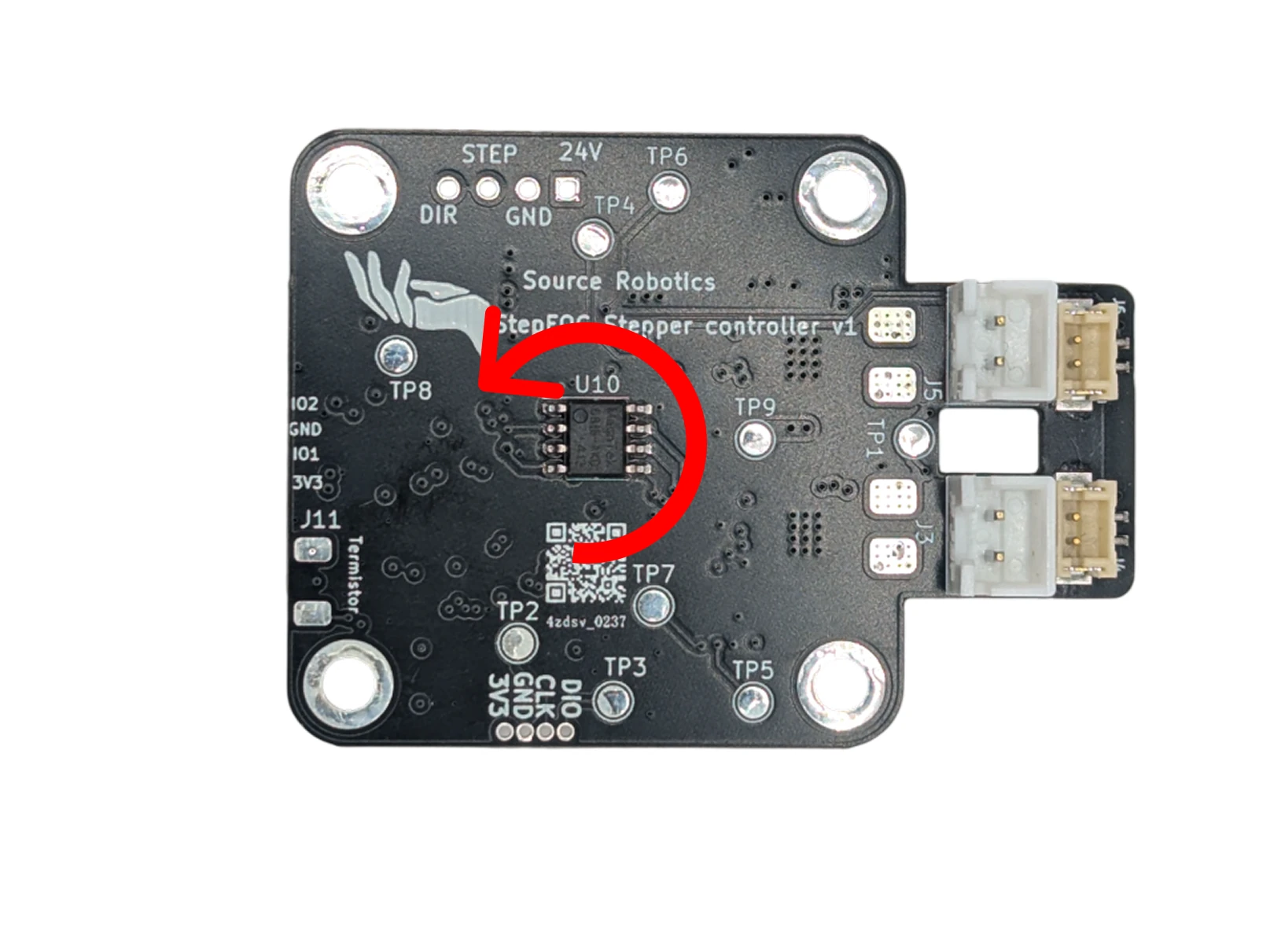
- Position is in encoder ticks: 16384 per revolution of the motor shaft, counting up without limit over several revolutions. Positive is counter-clockwise seen from the magnet (the back of the motor).
- Speed is in encoder ticks per second: 16384 is one revolution per second, 60 rpm.
- Current is in mA. Torque is current times the motor's Kt, which calibration finds.
- Feedforward: the 8-byte motion frame carries a speed and a current feedforward beside the position, the 5-byte one a current feedforward beside the speed. They are added after the loops, so a host that knows the trajectory can command it directly and leave the loops to correct the rest. Send 0 when you do not use them.
Try it
As a position: 1.000 turns, 360.0° · as a speed: 60 rpm · the practical maximum for 50 pole pairs is about 720 rpm
Torque: 0.21 Nm, 21 N·cm
The units of this page, with your numbers: 16384 encoder ticks per turn, the practical speed limit from the electrical frequency the control loop can follow (Ratings and limits), and the torque as Kt times the current.
Open-loop stepping
#Openloop and #gosteps drive the coils like a plain stepper driver, without the encoder in the loop. Like every
other mode, they need a calibrated driver without errors.
#Openloop 50turns the field at 50 electrical rad/s and keeps turning until another command. On a motor with 50 pole pairs that is 50 ÷ (2π × 50), about 0.16 revolutions per second.#gosteps 64makes 64 microsteps, then goes to idle; a negative number goes the other way.#microstep(16 by default) is the number of microsteps per electrical cycle, which is four full steps: with 16,#gosteps 16turns a 1.8° motor by 7.2°.#stepinterval(1000 µs by default) is the time between two microsteps, rounded down to whole control cycles of 160 µs.#Openv(5000 mV by default) is the voltage both put on the coils.
None of these settings is saved.
Open loop is not current-limited
Open loop applies a voltage, not a current, and #Ilim does not apply. At standstill and low speed the coil
current is about #Openv ÷ R: the default 5000 mV drives about 4.5 A through a 1.1 Ω coil, more than the
driver's 2.8 A and the motor's rating. Set #Openv to the rated current × R first (2 A × 1.1 Ω = 2200 mV), and
keep the test short.
Positive rotation
Which mode am I in?
#Mode prints the mode: Idle mode, Position control, Speed control, Current control, PD control,
Open loop, Gripper mode or Gripper calib mode. In this firmware release the voltage-torque mode reads
Gripper mode too (a leftover label), and HALL mode, the angle-offset search (#Calangle), open-loop steps
(#gosteps) and gripper mode print nothing. The behaviour of the motor is the reliable check there.
Comments
Found a mistake on this page? Edit it on GitHub · Report it · Get help · This page as Markdown · llms.txt · The whole manual as PDF