The encoder magnet
The encoder reads a diametrically magnetised magnet on the rear end of the motor shaft. The magnet must sit centred on the shaft's axis, parallel to the board, about 1 mm above the encoder chip, and it must not move.
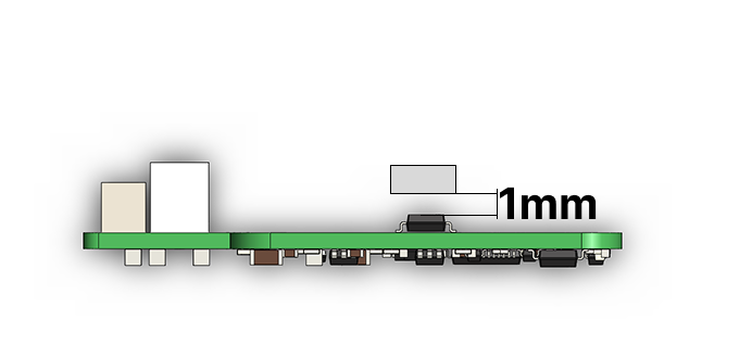
The magnet
A neodymium disc, diametrically magnetised (north and south across the diameter, not through the thickness). The shop's 6 × 2.5 mm diametrical magnet is the size the printed spacers are made for. An axially magnetised magnet looks the same and does not work: the magnet test may even pass, and the position is wrong.
The size is not fixed
6 × 2.5 mm is the stock size, not a requirement. Any diametrically magnetised disc of about 6 mm diameter works, and the thickness is a way to set the gap: a thicker magnet brings its face closer to the encoder, a thinner one farther, so with a shaft or a spacer that leaves the wrong distance you can pick the thickness that gives 1 mm instead of changing the spacer. What matters is the 1 mm from the magnet's face to the chip, the magnet centred on the shaft, and the diametrical magnetisation.
Fitting it
- The motor needs a rear shaft. Most NEMA 17 motors have one; a motor without it needs a magnet holder on the front shaft and a different mechanical layout.
- Press the magnet onto the shaft centred. The magnet tool in the firmware repository is a printed jig that centres it; a 3D-printed magnet spacer from Stepper motor accessories fits between the shaft and the magnet when the shaft is too short.
- Fix it with a drop of glue. A magnet that can turn on the shaft is the classic cause of a calibration that reports success and a motor that then runs badly: the magnet slipped between calibration and use.
- Check the height after the board is mounted: with the spacer for your motor length, the gap is 1 mm. A magnet that touches the chip can destroy the microcontroller; a magnet 2 mm away or more gives a weak signal.
Checking it
With the driver powered and the serial terminal open, #Magnet answers Magnet Good when the chip sees enough
field, Magnet Bad when it does not. The calibration routine runs the same test first.
What the magnet test checks
Only that a magnet is close enough to the encoder. It passes with a magnet that is not glued, sits off-centre or can slip on the shaft, and fails only when there is no magnet or it is too far away. The 1 mm gap, the centring and the glue are yours to check.
Comments
Found a mistake on this page? Edit it on GitHub · Report it · Get help · This page as Markdown · llms.txt · The whole manual as PDF