Dimensions and CAD
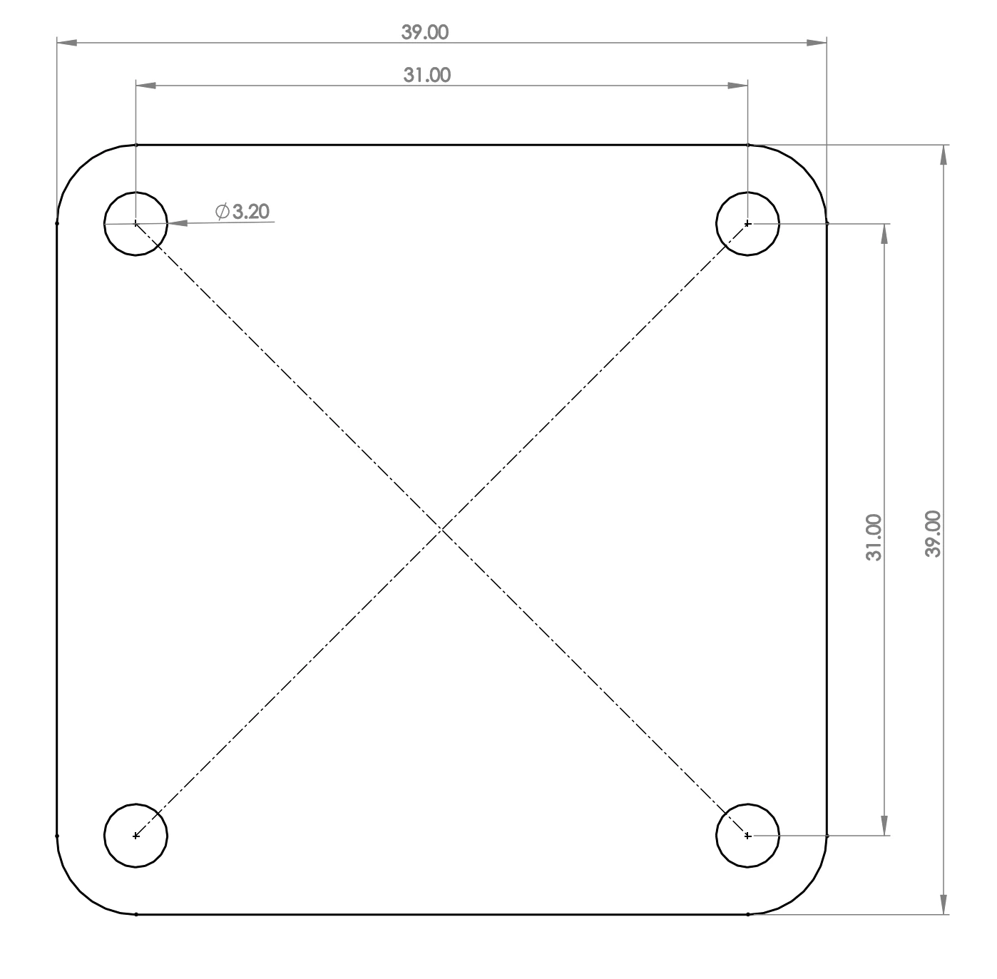
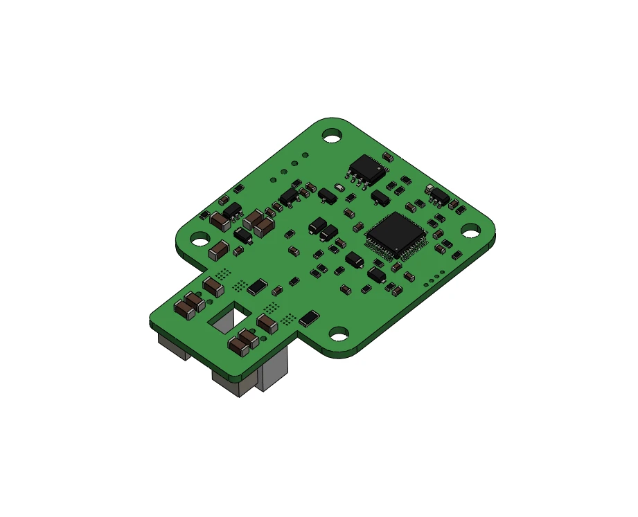
The board is 39 × 39 mm with the four mounting holes on the NEMA 17 pattern (31 mm apart), so it bolts to the back of a NEMA 17 motor with the motor's own screws and a spacer. The encoder chip is exactly in the middle of the board, on the motor shaft's axis.
Drag to turn the board, scroll to zoom. The model is the board's STEP file from the repository, the PCB and everything mounted on it.
The STEP files of the board, the magnet spacers for different motor lengths and the tool for pressing the magnet onto the shaft are in the firmware repository:
- STEP files of the board
- Stepper motor accessories: magnet spacers, NEMA 17 spacers for different motor lengths, NEMA 23 spacers
- Tools: the magnet tool
Downloads and files lists everything that can be downloaded.
Comments
Found a mistake on this page? Edit it on GitHub · Report it · Get help · This page as Markdown · llms.txt · The whole manual as PDF