Force and speed
A move command carries a current limit in mA and a speed from 0 to 255. This page estimates the resulting force and speed. Force and payload values are ideal model estimates, not measured ratings.
Grip force
The driver limits the motor's current to the value you command, so the torque the motor produces is limited to \(T = K_t \, I_q\), with \(K_t\) the motor's torque constant in Nm/A and \(I_q\) the current limit in amperes (the command is in mA). The pinion shares that torque between two racks. Here \(F\) is the combined normal force of both jaws, not the force at one jaw:
\(K_t\) = 0.325 Nm/A is the assumed torque constant used by this model and \(r\) the pitch radius of the pinion. They give an ideal combined force of about 54 N per ampere: about 8 N at 150 mA and 80 N at 1.5 A.
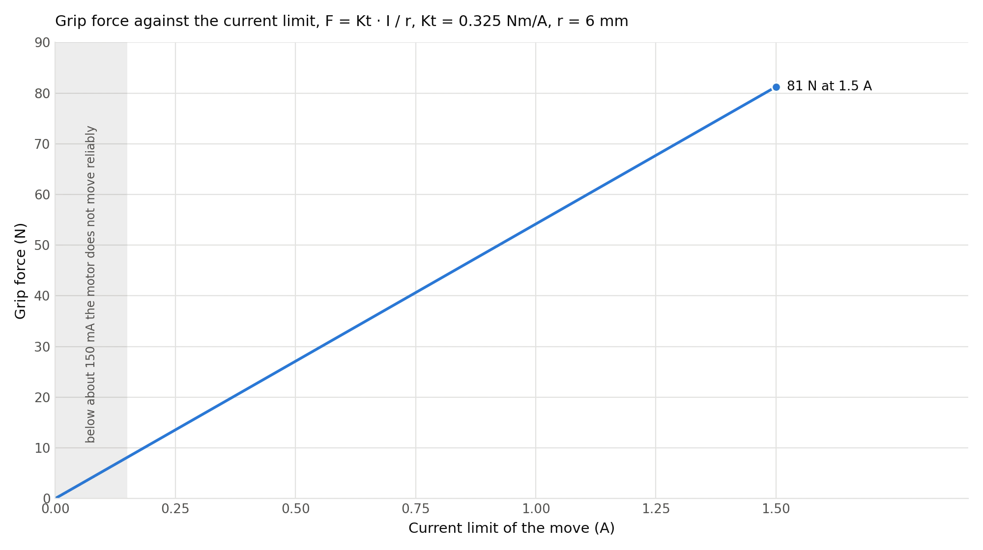
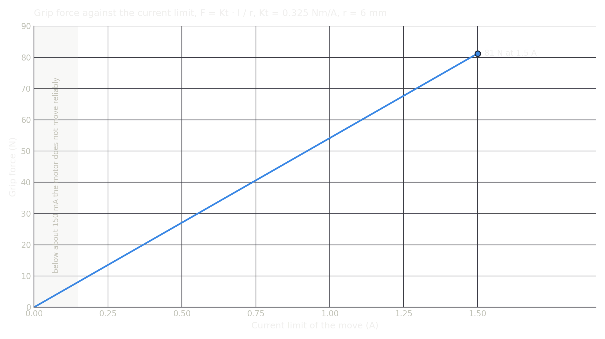
The curve is computed from the assumed torque constant, rather than a measured force calibration. #Kt
over UART prints the driver's torque constant; that value must match its \(q\)-axis current convention. A
datasheet current rating or supply current cannot be substituted directly. Measure your gripper with the
fingers and contact position you will use; below about 150 mA the motor does not move reliably.
The reported force-gauge result is about 48 N/A, but its per-jaw versus combined-force convention is not specified. Keep it separate from the theoretical combined-force curve until the measurement setup is known.
The current limit caps motor torque; it does not guarantee that the commanded current or the estimated contact force is reached. Mechanism friction, finger flex and the contact position affect the actual force.
Heat
The firmware does not clamp the gripper's current. A hold at 300 mA ran for 24 hours (Performance tests); a hold at 1600 mA trips the 75 °C thermistor limit after four minutes. Use high currents for the grip and a low current for the hold.
For a symmetric grip, each jaw applies \(F/2\). The torque balance is \(T = F_\mathrm{left} r + F_\mathrm{right} r = F r\); counting \(F\) once for each jaw would count the motor's torque twice. These are theoretical forces before losses in the mechanism. A compression gauge between the jaws reads the force at one contact; double that reading before comparing it with the combined force here. Record the current, fingers and contact position when measuring; the same setup is needed for a useful comparison.
Try it
Ideal combined grip force 16 N · estimated static payload 0.25 kg with the chosen friction and safety factor
Each jaw 22 mm/s · the jaws close at 43 mm/s · the full stroke takes 1.1 s
The formulas of this page, with your numbers: the force from the current, the weight held by friction with the safety factor of the next section, and the speed from the speed byte.
Payload
The grip force is not the weight the gripper can lift. An object held by friction between the two jaws is held by \(\mu(F_\mathrm{left} + F_\mathrm{right}) = \mu F\), with \(\mu\) the friction coefficient between the fingers and the object. Dividing the available friction force by a chosen safety factor \(S\) gives the static estimate:
Using an assumed \(\mu\) = 0.3 and \(S\) = 2, the model gives about 12 N of supported weight (1.2 kg) at 80 N of combined grip force. This is a static estimate. Upward acceleration of 1 g doubles the load; acceleration and emergency-stop loads need a separate check. Friction can be lower than 0.3, so measure it with your fingers on your object. A form-fit grip needs its own load assessment.
Speed
The speed byte of a move is mapped by the firmware to the motor's speed in encoder ticks per second, linearly from 40 at speed 0 to 80000 at speed 255:
The motor's encoder has 16384 ticks per revolution, so the angular speed is \(\omega = \text{ticks/s} / 16384 \times 2\pi\) and each jaw moves at
| Speed byte | Motor speed | Each jaw moves at | The jaws close at |
|---|---|---|---|
| 0 | 40 ticks/s | 0.1 mm/s | 0.2 mm/s |
| 20 (the power-up default) | 6300 ticks/s, 0.4 rev/s | 15 mm/s | 29 mm/s |
| 30 | 9400 ticks/s, 0.6 rev/s | 22 mm/s | 43 mm/s |
| 128 | 40200 ticks/s, 2.5 rev/s | 92 mm/s | 185 mm/s |
| 255 | 80000 ticks/s, 4.9 rev/s | 184 mm/s | 370 mm/s |
Both jaws move, so the gap closes at twice the speed of one jaw. At speed 255 the 48 mm stroke takes well under a quarter of a second. The gripper calibration runs at speed 40 and 500 mA.
Position
The position byte is linear over the stroke: 0 is the fully open end stop found by the gripper calibration, 255 the fully closed one. One step of the byte is 48 mm divided by 255, 0.19 mm. The driver considers the position reached within 5 encoder ticks, about 0.01 mm.
Comments
Found a mistake on this page? Edit it on GitHub · Report it · Get help · This page as Markdown · llms.txt · The whole manual as PDF