Calibration
Spectral firmware has autocalibration feature that allows you to automatically detect and tune your motor parameters. It detects the following:
- Motor phase resistance
- Motor phase inductance
- Motor pole pair
- Motor phase order (checked; if it is wrong you are told to swap two phases)
- Current loop PID parameters
- Motor Kt, KV and flux linkage
- Fine tune electrical angle
Vbus voltage
When calibrating the motor use 24V supply voltage for the best results! Using smaller voltage may result in incorrect Resistance, inductance and kt and other parameters!
Positive rotation
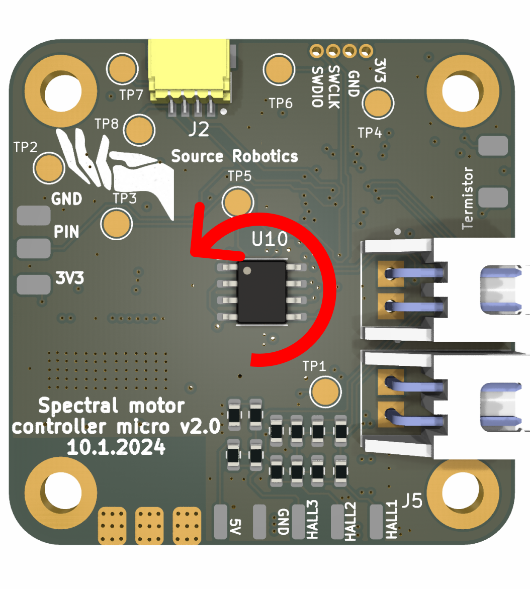
In spectral firmware positive rotation is always counter-clockwise. That means that positive current will result in rotation in that direction. Positive speed setpoint will rotate motor in that direction and rotating in that direction will increase motor position!
Default calibration settings
Calibration default setting are:
- Current loop bandwidth: 500.00Hz -> Used to calculate current loop PI parameters, setting this too high will result in vibrating motor and audible noise
- Resistance voltage: 1000mV -> We start to measure resistance at this voltage and increase it until power dissipation reaches the "Max Power dissipation" parameter below
- Max Power dissipation: 12.00W -> Used for resistance measure and as a maximum that we can dissipate when calculating inductance
- Open loop voltage: 5000mV -> What voltage we will use for open loop control (used to calculate Pole pairs)
- Open loop Speed: 20.00Rad/s -> Electrical speed we will use for open loop (used to calculate Pole pairs)
- Phase search voltage: 5000mV -> Used when spinning the motor to find the correct phase order
These generic parameters work for motors with a phase resistance of 2 to 24 ohms.
Danger
Using these settings on motors with lower resistance (for example Drone BLDC motors) can be destructive for Spectral BLDC driver.
Note
Resistance and inductance values returned from calibration will have variations and are just estimates of real values.
Note that the values that Spectral drives calculate are only estimations and if you want to get exact values use high precision instruments to measure them.
Calling calibration routine
Calibration routine can only be called from the UART interface. The command is:
#Cal
Calibration routine output
Note
Values that our calibration routine returns here are specific to motor we tested. Your numbers WILL be different!
Tip
In case your motor stays in one step of the calibration routine too long issues a #reset command and try again. Also do that in case you don't get full log messages from the routine.
After calling calibration routine the following will happen:
Window with default calibration settings
These are the setting that will be used for calibration
Calibration mode
-----Settings-----
Current loop bandwidth: 500.00Hz
Resistance voltage: 1000mV
Max Power dissipation: 12.00W
Open loop voltage: 5000mV
Open loop Speed: 20.00Rad/s
Phase search voltage: 5000mV
Magnet and Vbus check
Motor will check Vbus voltage and try to detect Encoder magnet. If both passed you will get:
Magnet test: Passed
Vbus test: Passed
Even if the magnet test "passed" your magnet could still be too far or too close (touching) the encoder IC. You need to make sure that distance between the magnet and the IC is 1mm.
Resistance and inductance measurement
In this step the motor produces clicking sounds while the driver measures the resistance and the inductance.
The output will be as follows:
Resistance = 7.026575Ohm
Inductance = 0.001492H
Kp_iq = 1.288308
Ki_iq = 0.630704
Motor will also calculate Kp_iq and Ki_iq using measured resistance, inductance and given current loop bandwidth.
Pole pair check
Motor will spin in one direction to check the number of pole pairs.
Output will look like this:
Pole pair = 11
Phase wire disconnected
Motor is wobbling left and right during calibration? One of your motor wire phases is disconnected!
Phase order
Motor will start to spin in both directions.
Good output will look like this:
Phase order = 2
Phase order is good!
In case you get:
Phase order = 0
Phase order is wrong!
Switch motor phases and try again!
Calibration failed!
Power off the motor and switch any 2 motor phases. Re run the calibration. If you get the same error again switch motor phases again until you get:
Phase order is good!
Kt, KV and flux linkage
Motor will start to spin fast in one direction for a short time.
Good output will look like this (Your numbers will be different):
KV is: 39.41667
Kt is: 0.20981
Flux linkage is: 0.012716
Errors
Note that in this step we measure motor KV and from that Kt and flux linkage. KV measurement can be wrong due the a lot of factors and for cheap and poor quality motors you can get different results in by 2-3 times magnitude.
Calibration end
In case your calibration was successful you will get message like below. Make sure to save the config.
After the successful config is saved you don't need to re run calibration when you start your motor driver.
Calibration success!
Save config with #Save
Going to idle!
Note
You will need to re run the calibration if you change your motors or change motor phases.
False success!
There is a known issue related to the encoder magnet's attachment to the motor rotor. If the magnet is not securely fastened and can slip or rotate freely, the motor may incorrectly report that the calibration process was successful when, in fact, it was not. To avoid this problem, it's crucial to ensure that the magnet is firmly secured to the motor rotor. Proper attachment of the magnet ensures the accuracy of the calibration process and prevents potential errors in motor operation.
OPTIONAL Encoder zero and electrical zero align
In a Field-Oriented Control (FOC) system, we want the \(I_q\) current to produce pure torque, while \(I_d\) produces the magnetic field. But when those two “zero points” don’t line up, the controller ends up injecting some \(I_q\) into \(I_d\). This is called cross-coupling, and it leads to a few tell-tale symptoms:
- Asymmetric torque: Forward and reverse torque constants (\(K_t\)) come out different.
- Extra heating: Part of the current is wasted creating unwanted field instead of torque.
- Reduced efficiency: The motor draws more current for the same torque.
The fix? Properly calibrate your electrical angle (often called the theta offset) so that your encoder’s zero aligns with the motor’s true electrical zero. Once they match, \(I_q\) becomes pure torque in both directions, torque symmetry returns, and your motor runs more efficiently and cooler.
After you ran #Cal command you need to run #Calangle command.
Your motor will start to spin in one direction and then switch to another multiple times. This process can take up to 2 minutes, if it takes longer it will timeout and return that theta_offset is 0.00 (You can check what current theta_offset is by typing #Offset). If it is successful you will see that #Offset will return some value different from 0. To check it again you can command motor to spin in one direction with some current setpoint like #Iq 500, and note the speed with #V. Then do the same for #Iq -500 and note the speed with #V. The speeds for both directions should be around the same value.
After you ran #Calangle and you confirmed it was successful you need to run #Cal again to re-calulate correct Kt and KV values.
Troubleshooting
No magnet detected
Magnet test: Failed
Vbus to low or not detected
Vbus test: Failed
Motor is not connected or damaged
Resistance test: Failed
Wrong phase order. Switch motor phases
Phase order is wrong!
Switch motor phases and try again!
Calibration failed!
If calibration is successful but your LED is in error mode and calling #Error reports no error try to call #Info command. If you see -1 somewhere that means that the default config was not loaded and the EEPROM is filled with junk values. To fix that call the #Default command.
Found a mistake on this page? Edit it on GitHub · Report it