Spectral micro datasheet
Spectral Micro is a brushless motor controller designed to offer affordable and capable hardware, complemented by open-source software. It supports multiple firmware options and integrates a 14-bit magnetic encoder, inline current sensing, CAN and UART data interface, and provides support for position, velocity, torque, and impedance control.
Everything you need for developing high-performance robotic solutions is included.
It is ideal for gimbal motors, quadrupeds, robotic arms, and grippers. See the list of tested motors.
| Features | |
|---|---|
|
Electrical specs - 3 phase brushless FOC controller - Voltage input: 12 - 29V - Max continuous phase current: 2.8A - Max phase current: 2.8A (with good cooling) - Inline current sensing - PWM switching rate: 25 kHz - Max power: 80W - Idle power: 0.3W - Control loop frequency: 5kHz - Max electrical frequency: 460 Hz Mechanical specs - Mass: 8 g - Dimensions: 39mm x 39mm - Nema 17 compatible mounting hole distances Features - STM32f103c microcontroller - 14 bit encoder - CAN and UART communication - Daisy chain CAN and power connector - EEPROM memory 16 Kbit - Hardware overcurrent, over-under voltage and temperature protection - Fully open source firmware and support for SimpleFOC - One additional pin analog input, digital input or output - Temperature sensor connector - Torque, velocity, position, and Impedance control modes - Auto calibration features |
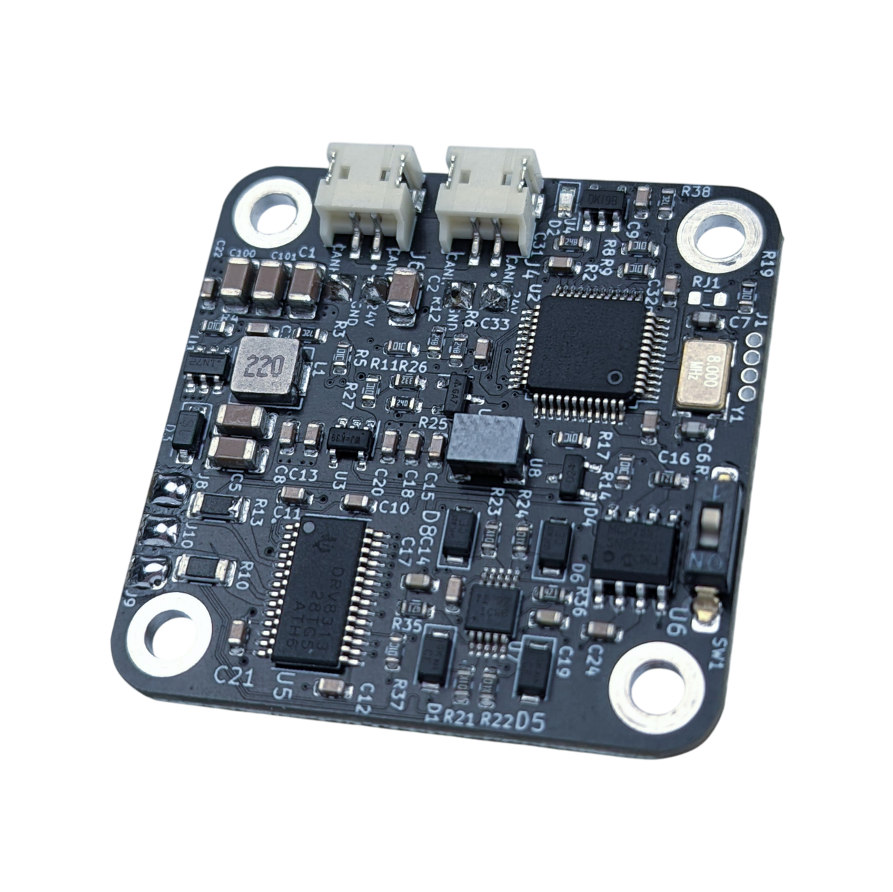
Each spectral micro BLDC controller is Fully end of line tested.
Absolute maximum ratings
- Supply voltage -> min 10V, typ 24V, max 29V
- Phase current -> typ 1.5A, max 2.8A
- Operating Temperature -> min -20°C, typ 25°C, max 130°C
Hardware level protection circuits and limits:
- Overcurrent protection trip level -> min 3A typ 5A
- VM undervoltage lockout voltage -> typ 6.3V MAX 8v
- Thermal shutdown temperature -> min 150 deg, typ 160, max 180
Connectors
| Connector | Cable assembly | Connector datasheet |
|---|---|---|
| UART | UART cable | JST SH series |
| Power | Power cable | JST XH series |
| CAN | CAN cable | JST ZH series |
| JTAG | Programming adapter | 1.27 pitch pin header |
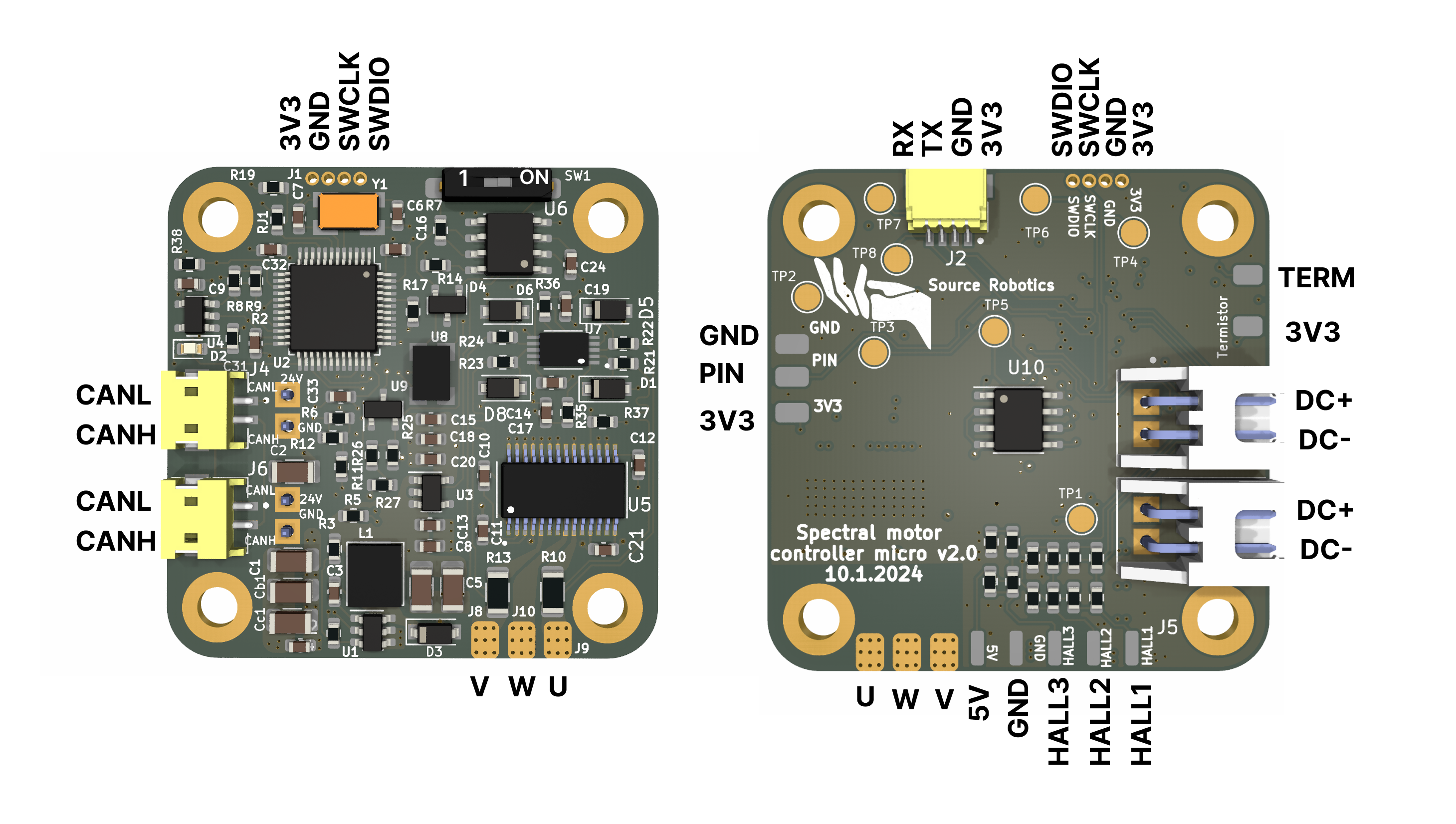
Pinout
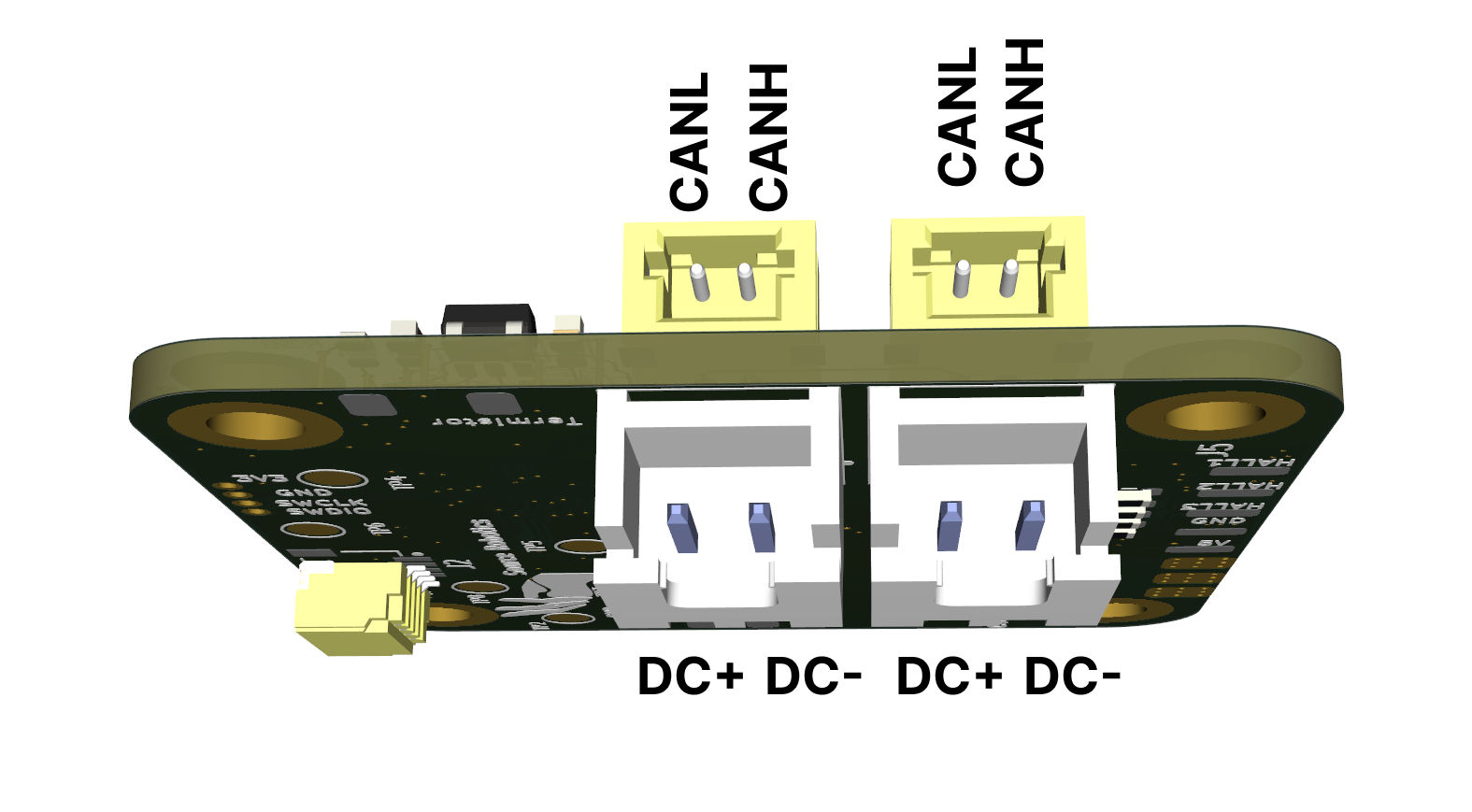
Reversing the polarity on DC+ and DC- will destroy the board.
Motor phases are connected to U, V and W. Power is connected to DC+ and DC-
Note!
- to enable hal you need to solder 12 10k resistors above HAL connector
- thermistor pin is using pulldown of 54.9 kilo ohms.
- UART is 3v3 only. Using 5V will destroy the board.
- "PIN" can be used as analog input or general purpose input/output
CAD and dimensions
Download the Spectral Micro STEP files
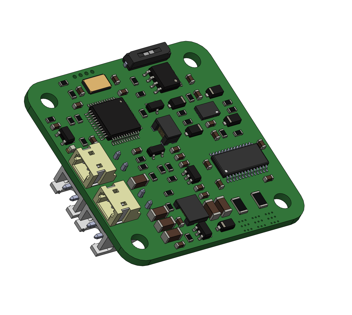
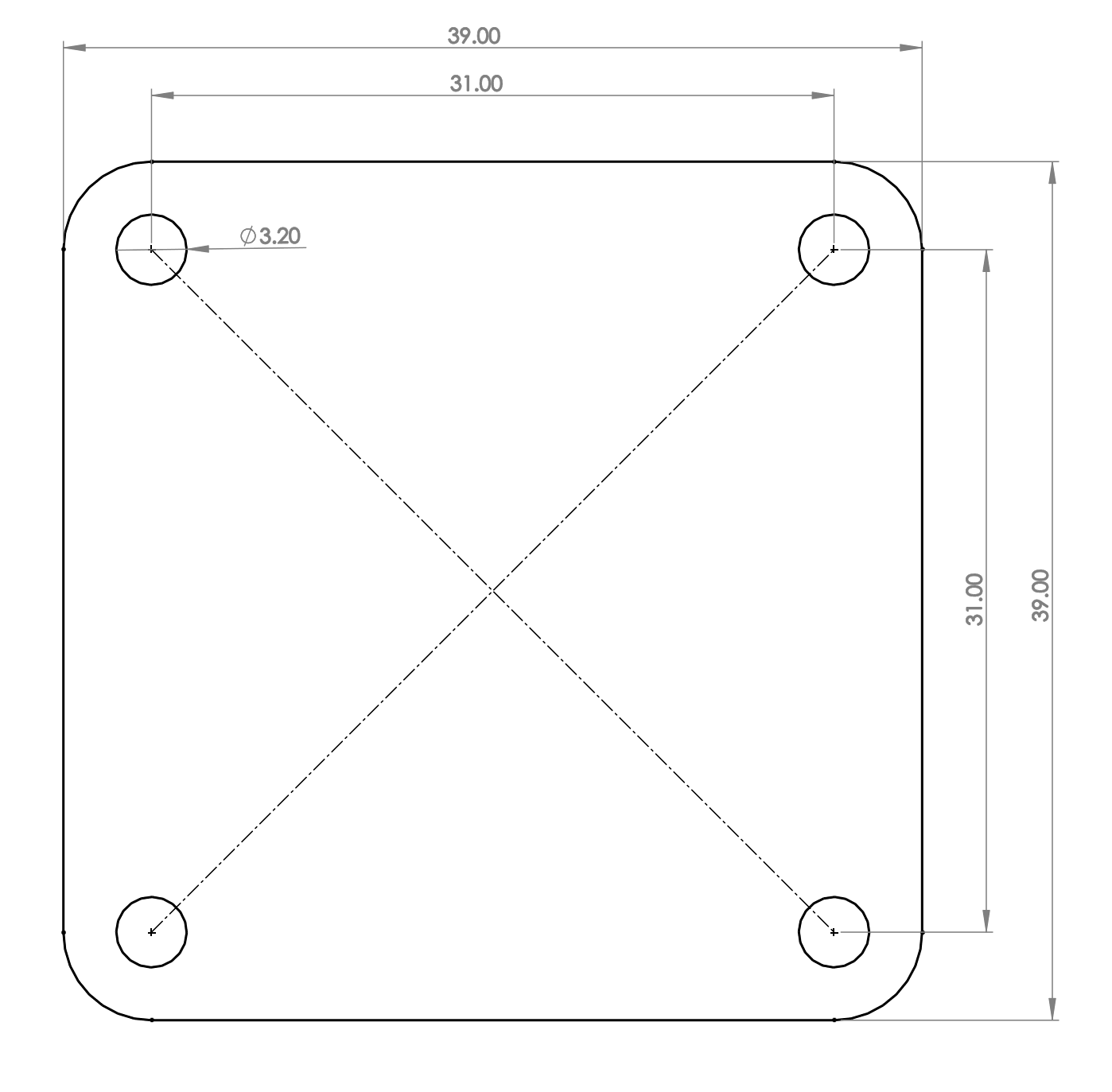
Spectral micro uses same hole spacing as NEMA17 format motors.
Magnetic encoder is located exactly at the middle of the board!
CAN termination
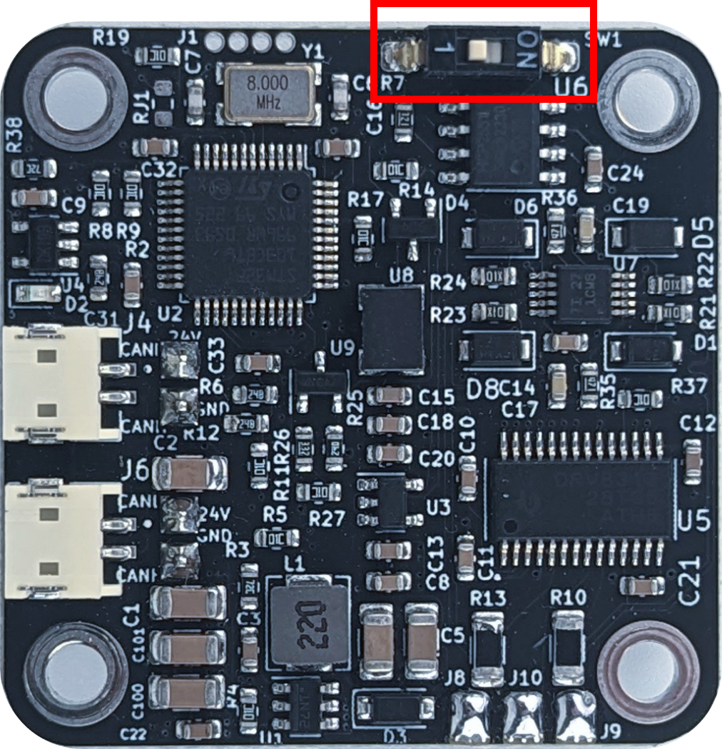
To use CAN termination make sure to place the switch in ON position!
Pre loaded firmware
Spectral Micro comes preloaded with the Spectral firmware. Check which release with the UART command #Info.
Default settings that come preloaded are:
- LED indication: 1
- Calibrated: 0
- Using thermistor: 0
- Watchdog active: 0
- Heartbeat active: 0
- UART baud rate: 256000
- CAN baud rate: 1000000
- Default CAN node ID: 0
- I AM GRIPPER: 0
Found a mistake on this page? Edit it on GitHub · Report it