Current limit and loop tuning
Calibration leaves the driver with current loop gains computed for your motor and with velocity and position gains that suit a bare stepper.
Two things remain: the current limit, which you must set for your motor, and the loop gains, which you tune if the defaults do not suit it. Motor GUI shows the motor's response on its plots while you change a gain, which is what makes tuning quick.
The current limit
Set the current limit to the rated phase current of your motor in mA (the datasheet value; the tested motors' ratings are in Tested motors).
It is 1700 mA after #Default;
calibration uses its own 1600 mA for its steps and, from firmware 109, puts your limit back when it ends. Set it
before you calibrate: the encoder table that follows a calibration runs at 80 % of it.
#Ilim clamps the limit to
the driver's 2800 mA and takes the magnitude of a negative number. The
firmware does not trip on phase current by itself and does not monitor the driver stage. A limit above the motor's
rating overheats the motor.
Over CAN
From firmware 109 Send_Limits stops the current limit at 2800 mA, as #Ilim does, and ignores a negative
value. Firmware 108 and older stored it as sent (known issue KI-1). A host program must still keep it within
the motor's rating.
Crunching and whining sounds at speed usually mean the current limit, or the current loop gains, are too high.
The loops
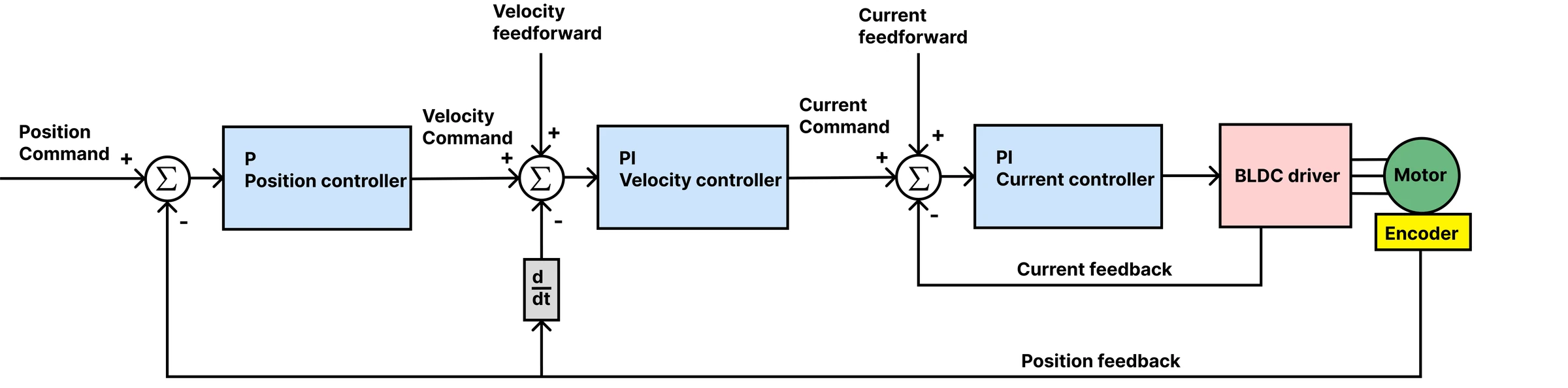
Tune from the inside out: the current loop first, then velocity, then position. Before you start:
- The motor must be calibrated and without active errors; the driver refuses the control modes otherwise.
- Fix the motor to the bench, nothing on the shaft. A loop that oscillates can shake a loose motor off the table.
- If the defaults oscillate, lower all gains until the motor is quiet, then raise them one at a time in small steps.
The gains are in the settings: change one, Apply gains, command a move with the jog controls and read the
response on the plots. Apply preset loads a starting set for a kind of motor: a product preset writes its
own current and velocity gains; the Generic motor presets set soft limits and velocity gains and leave the
current gains to #Cbw and the calibration. Apply a preset before you calibrate, so that the calibration
computes the current gains, and set the velocity gains after it. Save when you are done.
Each gain is a command: #Kpiq 0.5, #Kpv 0.02, …, then #Save. Command a move with #Iq, #V or #P
and judge the response by ear and by #Cyc 20, which streams position, speed and current.
The current loop
The current loop is a PI controller that turns a current request into a voltage. Its gains Kpiq and Kiiq
follow from the motor's resistance R, its inductance L and one number, the bandwidth: Kp = ω·L and Ki = ω·R, with
ω = 2π × the bandwidth.
The firmware keeps Ki per control loop: Kiiq is about ω·R × 160 µs. For 1.1 Ω, 2.6 mH
and 160 Hz that gives Kpiq 2.70 and Kiiq 0.177.
Do not enter ω·R as #Kiiq. The PI then cancels the coil's
own lag, and the current follows a request like a first-order filter at that bandwidth. Calibration computes
them this way at 160 Hz, the default; so does setting the bandwidth:
The bandwidth can be 10 to 625 Hz (a tenth of the 6250 Hz control loop). A higher one follows a request and rejects a disturbance faster, and is louder; on the bench, 160 Hz followed an injected ripple better than the old gains and stayed stable.
Gains set by hand with #Kpiq and #Kiiq work too; parameter 49 then tells which
bandwidth they amount to.
Drives calibrated with older firmware
Firmware 108 and older divided both gains by 7, a loop of about 70 Hz. Their saved gains stay as they are
after an update to 109: parameter 49 reads about 71 Hz until the drive is calibrated again, or #Cbw 160 and
#Save are sent. See Upgrading from older firmware.
Test with a current setpoint of a few hundred mA (Jog current, or #Iq 300): the motor should push with a
steady, quiet torque. Keep the current well under the limit.
The velocity loop
The firmware's start values are Kpv 0.02 and Kiv 0.001, tuned on the bench with a bare NEMA 17 and the speed
estimate below: it vibrated at Kpv 0.056, and 0.02 is about half of that; Kiv rang at 0.004, and 0.001 halved
the speed ripple at 300 to 1500 ticks/s. #Default and a settings reset write the same values.
A drive saved
with older firmware keeps its saved gains after an update (typically 0.007 and 0.0005): set #Kpv 0.02 and
#Kiv 0.001 and #Save (a 21.5 mm stepper overshot 95 % at these on the bench; its presets use #Kpv 0.014
and #Kiv 0.00014). To tune for your motor and load:
- Raise
Kpvuntil the motor vibrates at a steady speed command, then take about half of it. - Raise
Kivslowly until the speed rings after a change, then back off well below that.Kivis an integrator: too much makes the motor unstable, none leaves a steady-state error. - Test with a speed setpoint (Jog velocity, or
#V 20000; 16384 ticks per second is one revolution per second) and with different speeds.
A motor geared into a joint carries more inertia than a bare one and usually takes other gains; tune it in place.
The position loop
- Raise
Kppuntil the motor overshoots or oscillates when it reaches a target, then back off. - Test with a position step (Jog position, or
#P 16384and#P 0): one revolution and back. The response should be quick, without overshoot; the plot shows both.
Testing
Run the motor over the whole range of speeds and loads it will see, with a load if you can, and adjust. Then save.
The speed estimate
The velocity loop needs the speed, which the driver estimates from the encoder count. Parameter 50 picks how:
| Parameter 50 | Estimate | How it behaves |
|---|---|---|
| 0 | moving average of the last 20 count differences | about 1.5 ms late, in steps of 312 ticks/s: the old estimate |
| 1 | PLL, the speed is its integrator | smooth, a little late |
| 2 (default) | direct PLL, integrator plus the proportional term | almost no lag, a little more noise |
Both PLLs are critically damped at the natural frequency of parameter 51, 60 Hz by default (10 to 312 Hz).
The
lag of the moving average was what limited the velocity gain: on the bench the direct PLL at 60 Hz allowed 40 %
more Kpv before the motor vibrated, and the speed ripple was 23 to 50 % lower at 1500 to 24000 ticks/s; its
extra noise did not reach the current.
Calibration and the gripper's stop detection always use the moving average, which they were tuned with. Both parameters are not kept by Save: every power-up starts with the direct PLL at 60 Hz. The speed in Respond_data_pack_1 and Send_Respond_Encoder_data, the watchdog descend and the capture is the picked estimate.
Commutation delay compensation
The voltage a control loop sets reaches the motor later than the angle it was computed from was read: the rest of the loop, the wait for the PWM update and half a control period.
By then the rotor has turned on, and the voltage lands a little behind the angle it was meant for. Parameter 64 turns the output voltage forward by the angle the rotor covers in that delay, in the closed-loop modes above 100 ticks/s.
166 µs is the default, measured on the bench drive: the d-axis voltage against the cross-coupling the motor's inductance makes, at 12000 to 48000 ticks/s, fitted over 15 points. 0 switches it off; 1 to 500 µs are accepted. It is not kept by Save, so 166 µs is in force after every power-up.
The finer points of the velocity loop
Two settings for special cases, both off by default and not kept by Save:
- Position input filter, parameter 74 (Hz, 0 to 250). A host that sends positions at a fixed rate sends a staircase; without the speed the steps are all the loops see. The filter turns the staircase into a smooth path and makes its own speed from it, in position and PD modes. Use it only for a host that sends positions without the speed feedforward, at about the host's rate ÷ 12 (8 Hz for 100 Hz). On the bench it cut the tracking error of such a host from 1023 to 260 ticks at 12 Hz; with a host that sends the speed it made the tracking worse, so leave it off then.
- Velocity-integral deadband, parameter 75 (ticks, 0 to 2000). In position mode the velocity integral sees the position error less this band, so a holding motor stops pushing against a small error it cannot correct. It trades accuracy for holding current: on the bench 5 ticks took the holding current from 16 to 3.4 mA, and the mean error grew from 1.5 to 6.4 ticks.
Impedance (PD) mode
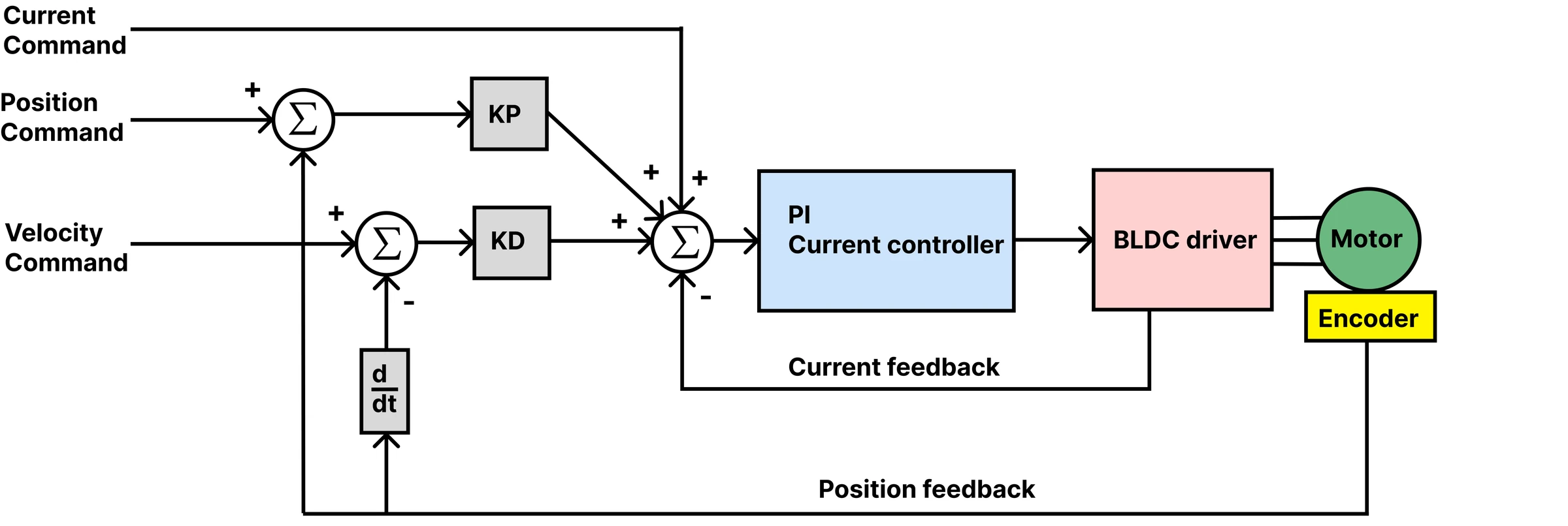
In PD mode the motor behaves like a spring and a damper: the current setpoint is
KP × (setpoint − position) + KD × (speed setpoint − speed) + feedforward current, in mA, with the position in
ticks and the speed in ticks/s. So KP is in mA per tick and KD in mA per tick/s.
Set KP and KD (the gains, or #KP, #KD, or Send_PD_Gains), then
command with #PD, #PDV and #PDI or Send_data_pack_PD. Start with a small KP and KD of 0, raise KP until
the motor holds position firmly, then add KD until it stops ringing. The theory corner
explains the loop.
Limits
- The velocity limit (
#Vlimit, 800000 by default) clamps the speed the loops may command, in encoder ticks per second. A rough maximum for your motor is 0.8 × V × KV × 16384 / 60 ticks per second, with KV from calibration and V the lower of the voltage limit and the supply voltage. - The voltage limit (
#Vlim) clamps the voltage of the current loops in mV. It is 6000 mV by default: a stepper's low resistance makes the current loop unstable with the full supply voltage, and the firmware's own guidance is 6000 mV for a phase resistance below 2 Ω. The limit also caps the top speed. 0, or a value above the supply voltage, uses the supply voltage. #Rstint 1resets the integrators on every new setpoint, which avoids windup when a program sends one setpoint after another with large steps.
Comments
Found a mistake on this page? Edit it on GitHub · Report it · Get help · This page as Markdown · llms.txt · The whole manual as PDF