Motor parameters and calibration
Calibration teaches the driver its motor. It:
- checks the magnet and the supply;
- takes the motor's resistance, inductance and pole pairs from you;
- computes the current loop gains;
- spins the motor in open loop to learn the direction of the wiring;
- finds the angle offset between the encoder and the motor's electrical zero;
- measures the motor constants Kt, KV and the flux linkage.
From firmware 109 two more runs follow by themselves, the encoder table and the anti-cogging, and then the driver saves everything. It runs once per motor; the result is kept by saving.
The motor turns
Calibration spins the motor in both directions, fast at times. Fix the motor to the bench and take everything off the shaft.
Supply voltage
Calibrate at 24 V. From firmware 109 KV and Kt no longer depend on the supply or on #Vlim: the spins that
measure them run at their own 6 V limit, and yours is put back afterwards.
1. Restore the defaults
The EEPROM of a new driver, or of one that ran another motor, can hold values that do not fit, such as another motor's parameters. Calibration starts from what is there, so start from the factory values.
(A damaged
configuration should not show up with firmware 106 and newer, which checks the stored blocks at power-up and
replaces a damaged one with the defaults; if #Info still shows -1 somewhere, restoring the defaults fixes it.)
This also resets the serial number, hardware version and batch date stored in the EEPROM, and clears an
encoder table and an anti-cogging set from another motor; note the hardware version and batch date #Info
prints if you need them. From firmware 109 the CAN node ID is kept. Saving the configuration says
what else it does.
2. Enter the motor parameters
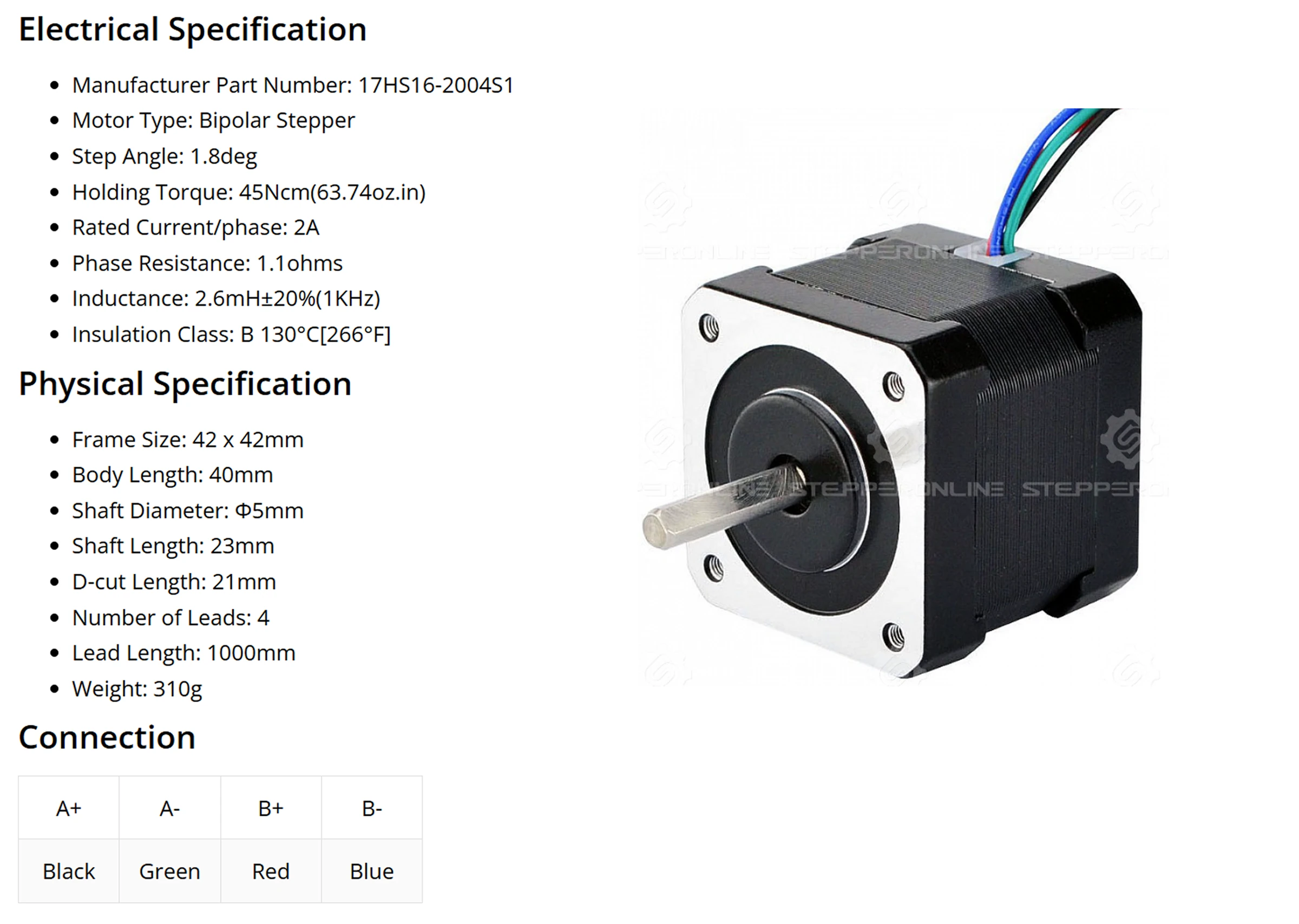
STEPFOC does not measure the resistance and inductance of a stepper (the Spectral Micro does for a BLDC); you enter them from the motor's datasheet, as the values of one coil, and the pole pairs. Calibration fails on a value left at 0, and accepts only 50, 75, 100 or 125 pole pairs.
We recommend a Motor GUI preset
In Motor GUI's Presets tab, a preset enters these values for you, with safe limits and gains. For a Source Robotics product, pick its preset. For any other stepper, pick Generic motor and type the pole pairs, the resistance and the inductance from the datasheet: the preset writes them with a low current limit and soft loops, so the motor calibrates safely. More: Motor GUI.
In the motor settings enter Pole pairs (50 for a 1.8° motor, 75 for 1.2°, 100 for 0.9°, 125 for 0.72°), Resistance in ohms and Inductance in henries, and apply them.
Parameters 78 (pole pairs), 76 (resistance in mΩ) and 77 (inductance in µH) hold the same values, for a host that sets a drive up over the bus: Send_Parameter(78, 50), Send_Parameter(76, 1100), Send_Parameter(77, 2600). The calibration itself runs over the serial port.
Calibration computes the current loop gains from R, L and the current loop bandwidth, 160 Hz by default: Kp = ω·L and Ki = ω·R, with ω = 2π × the bandwidth.
The firmware keeps Ki per control loop, so Ki_iq in the
log is about ω·R × 160 µs. Leave the bandwidth for now;
Current limit and loop tuning comes back to it. (Firmware 108 and older divided both gains by 7,
which gave a loop of about 70 Hz.)
3. Run it
The LED flashes fast while the routine runs, and the driver prints each step as it goes:
----------------
Calibration mode
----------------
Pole pair test: Passed
Magnet test: Passed
Vbus test: Passed
Resistance = 1.100000Ohm
Inductance = 0.002600H
Kp_iq = ...
Ki_iq = ...
Open loop direction: good
Calibrating angle offset... stage 1/13, sweep point 0
...
Angle offset is: ...
Alignment check: ... ticks/s, flipped ..., offsets ... / ...
Phase order is good!
KV is: ...
Kt is: ...
KV runs: ... ... ... ... (same direction within ... %)
Flux linkage is: ...
----------------
Calibration success!
Next, by itself: the encoder table, then anti-cogging (about a minute; keep the shaft free). Everything is saved when they finish (#Encal state, #Cogcal state)
Going to idle!
----------------
#Calonly runs the same calibration and nothing after it; it ends with Save config with #Save instead.
From firmware 110 #Estop or #Close stops a running calibration; #Idle does not. It ends as a failed
calibration (Calibration failed!): the motor is released, and the driver is not calibrated until it calibrates
again. After #Estop, send #Clear first.
On firmware 109 a reset (#Reset) was the only clean way over UART: #Close switched the mode under the running
calibration and left it half done.
What the steps are:
| Step | What happens | Fails with |
|---|---|---|
| Pole pair test | the entered pole pairs are one of 50, 75, 100, 125 | Pole pair test: Failed and the list of values |
| Magnet test | the encoder sees enough field: a magnet is there and close enough. The test says nothing about centring, the gap or the glue | Magnet test: Failed: magnet missing, too far, or axially magnetised |
| Vbus test | the supply is within limits | Vbus test: Failed |
| Resistance, inductance | the entered values are not 0; they are printed back and Kp_iq, Ki_iq computed from them and the bandwidth | Resistance test: Failed / Inductance test: Failed, with Please enter your stepper resistance by using #R command |
| Open loop | the motor is stepped open loop at a fixed 5000 mV. The direction the encoder saw is remembered, so a reversed coil is compensated from here on | nothing in this firmware: the step always reports good, and a motor that did not turn fails the next step |
| Angle offset | a short spin checks that the motor turns (two tries, 90 electrical degrees apart); then the field locks the rotor and a sweep finds the offset at which both directions turn alike. It prints Calibrating angle offset... with its progress every half second |
Phase order is wrong! / Switch motor phases and try again!: the motor did not turn on either try. A line Spin-confirm delta: … ticks (need > 8192), Vbus: … mV says how far it turned and at what voltage. When the lock or the check after it fails instead, Angle alignment gave up: names the reason (it timed out, the rotor did not turn under current or the rotor turned the wrong way, also after flipping), followed by Check speed … ticks/s (need > 1000), flipped …, offsets … rad and Try again; if it repeats, check the motor, its wiring and that the shaft is free |
| Kt, KV, flux linkage | four spins from standstill at 500 mA, about a second each and alternately forward and back, at a 6 V limit; KV is the mean speed per volt, Kt follows as 8.27 ÷ KV and the flux linkage from Kt. KV runs: in the log shows all four and how far they agree |
nothing: KV runs differ by more than 5 %: calibrate again, and check that the shaft is free is a warning, and the calibration still succeeds |
A whole run takes up to about a minute, most of it in the angle-offset search. When a step fails, the log ends
with Calibration failed!, the driver goes to idle, the motor counts as not calibrated and the LED stays on
steadily. Nothing is saved; fix the cause and run #Cal again.
The 'Switch motor phases' message
It is left over from firmware 103, which needed the coils wired a particular way. Since firmware 105 the
wiring is detected and compensated, so Phase order is wrong! / Switch motor phases and try again! means the
motor did not turn or did not respond: a coil not connected or shorted, a supply too weak, or a magnet that
slips. Swapping wires does not fix it. (Open loop: Failed with the same advice cannot appear in this
release.)
The measured values are estimates
KV, Kt and the flux linkage come from one short spin and differ a little from one run to the next, more on motors with uneven windings. For the loops this does not matter; for a torque estimate in newton-metres, measure Kt yourself.
What follows the calibration
Half a second after Calibration success! of a #Cal the driver starts two runs on its own: the encoder table
(about 20 s), then the anti-cogging identification with the current-sense zero trim (about 25 to 70 s). When they
succeed, everything is saved.
The motor turns slowly, one turn forward and one back for each run, so keep the shaft free for about a minute
more; #Info shows running: … under In force: while they go.
A command from a host (a motion command,
#Idle) stops them; then nothing is saved, and the calibration is kept only if you #Save it.
Encoder table and anti-cogging explains both and how to check them. #Cal always runs them;
#Calonly never does.
Set the current limit before you calibrate
The encoder table turns the field with a current of 80 % of the current limit, for about 20 s. Calibration uses
its own 1600 mA for its steps and puts the limit that was in force back when it ends, before the encoder table
runs; after #Default that is 1700 mA, about 1.4 A in the coils, more than a small motor is rated for. So set
#Ilim for the motor before #Cal (a Motor GUI preset does; known issue KI-19).
Not yet tested on the bench
The runs after a calibration and #Calonly were tested on the bench on 2026-11-10 (#Calonly 25 times on a
20 mm motor, #Cal with both runs on a 40 mm and a 60 mm motor). Parameters 76 to 79 and #Par came last in
firmware 109 and had not been tested on the bench when this page was written.
4. Save
After #Cal the driver saves by itself when the runs succeed; save anyway once they are done, or after
#Calonly. Without a save the calibration is gone at the next power cycle.
The driver goes to idle and the LED shows normal operation; the state shows Calibrated and the constants.
The current limit
Calibration uses its own 1600 mA for its steps. From firmware 109 it puts the limit that was in force back when
it ends, so a save stores your limit; firmware 108 and older left 1600 mA in force (known issue KI-2). If the
limit is still the 1700 mA of #Default, set it for your motor with #Ilim and save again
(Current limit and loop tuning).
Check
After a power cycle #Info prints Calibrated and the constants calibration found, and Motor GUI shows
Calibrated. Not calibrated means the save did not happen: calibrate and save again.
When to calibrate again
- After changing the motor, the magnet or the wiring.
- After restoring the defaults.
- After a firmware update that clears the calibration (a release note says so when it does).
A calibration that reports success but a motor that runs badly afterwards usually means the magnet moved on the shaft between calibration and use: fix the magnet and calibrate again.
Troubleshooting
| Message | Cause |
|---|---|
Magnet test: Failed |
no magnet, magnet too far (more than about 1.5 mm), or an axially magnetised magnet |
Vbus test: Failed |
supply off, too low, or the cable the wrong way round (if the driver survived it) |
Resistance test: Failed, Inductance test: Failed |
the resistance or the inductance still 0 |
Phase order is wrong! |
see the note above: the motor did not turn on the spin check; check the four wires and their solder joints, the supply and its current limit, and the magnet |
Angle alignment gave up: after Phase order is wrong! |
the lock or the check after it failed, and the line names the reason; run #Cal again, and if it repeats check the motor, its wiring and that the shaft is free |
Cal: not started, the E-stop is latched (#Clear first), or Stopped by an E-stop: #Clear, then calibrate again. after Calibration failed! |
an E-stop is latched or ended the calibration: #Clear, then #Cal; the alignment starts again from its first stage |
| the routine stops in a step and prints nothing more | stop it with #Close (firmware 110) or reset the driver (#Reset), and try again; the angle-offset search prints a progress line every half second, so wait for a minute before you decide |
| success, but the LED stays on and no error is reported | should not happen with firmware 106 and newer, which replaces a damaged configuration block with the defaults at power-up. If #Info shows -1 somewhere, restore the defaults, enter the parameters and calibrate again |
#Calangle runs an angle-offset search on its own, with an older routine than the one #Cal uses: it gives up
after about two minutes and keeps the offset it reached. From firmware 109, when parameter 56 is not 0, the
anti-cogging is identified again afterwards and everything is saved, because the anti-cogging depends on the
offset.
After a timeout nothing follows and nothing is saved. From firmware 109 #Calangle is refused while the
driver is in error: it prints Calangle: not started, the drive is in error (#Error, #Clear). After a change of
motor, magnet or wiring, run the whole #Cal instead.
Calibration runs over the serial connection only: a terminal, or Motor GUI over the serial adapter, not over CAN.
Comments
Found a mistake on this page? Edit it on GitHub · Report it · Get help · This page as Markdown · llms.txt · The whole manual as PDF