Encoder table and anti-cogging
Firmware 109 measures two corrections on the drive itself, with nothing but the motor on the bench. The encoder table corrects the small error of the encoder's angle reading. The anti-cogging is a current that cancels the motor's own torque ripple. The same routines run on the sister driver STEPFOC.
After Calibration success! of a #Cal both run by themselves, and everything is saved when they succeed
(What follows the calibration). #Calonly is the calibration
alone. This page explains what they are, how to run them again, and how to check them.
On the Spectral Micro bench (gimbal motor, 2026-11-10) a full #Cal measured the encoder table and identified the
anti-cogging, and saved both. Check the result (Checking them) before you keep it.
The motor turns
Each run turns the motor one revolution forward and one back, slowly. Keep the shaft free: nothing on it and nothing it could drive. A mechanism that cannot turn a whole revolution, a gripper's jaws for example, has to come off first.
The encoder table
The magnetic encoder reads the shaft angle with a small error that changes slowly around the turn. The magnet is never exactly on the axis, and the chip itself is not perfectly linear. On the bench gimbal motor it was 0.50° peak to peak.
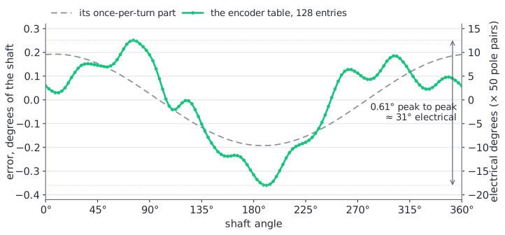
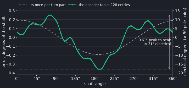
The STEPFOC bench stepper read 0.61 to 0.65° from run to run. Two of its tables agreed within 0.021°.
The commutation multiplies it by the pole pairs. On an 11-pole-pair motor 0.50° spans about 5.5 electrical degrees. The electrical offset sits near the middle of that span, so the field is a few electrical degrees off at places. That costs torque and makes the current uneven around the turn.
To measure it, the driver turns the field open loop, one shaft revolution forward and one back at 2048 ticks/s (about 20 s). A current of 80 % of the current limit holds the rotor to the field.
At each 1/128 of a turn it records how far the encoder's angle is from the field's. Forward and backward are averaged, so friction, which pulls the rotor behind the field in each direction, cancels. The motor's own pull at higher orders is left out by keeping only the harmonics 1 to 16 per turn.
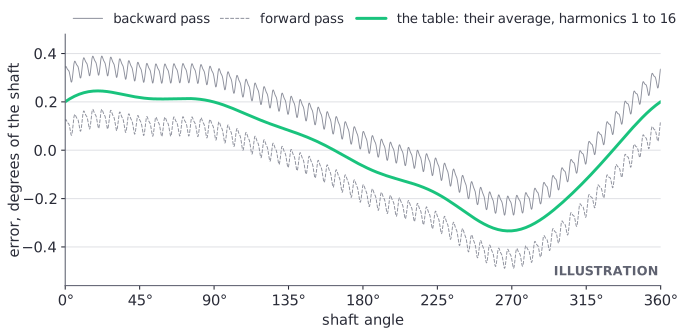
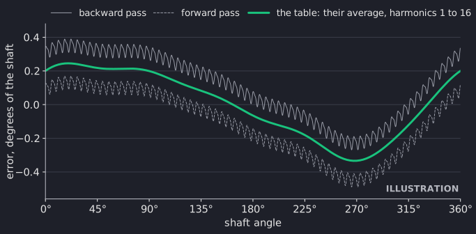
The result is a table of 128 corrections. From then on the encoder reading is corrected with it. The electrical offset is moved by the table's mean error, so the commutation stays right.
The plot shows a measured table from the sister driver STEPFOC, which runs the same routine, on its bench NEMA 17. Its right-hand scale multiplies by the stepper's 50 pole pairs. On an 11-pole-pair motor the same error is about 4.5 times smaller in electrical degrees.
A check of the routine on a simulated 11-pole-pair motor at the Spectral Micro's loop rate took the commutation error from 30 to 0.4 electrical degrees.
A table over 4° peak to peak, or one that would move the offset by more than 60 electrical degrees, is rejected as implausible: the magnet is loose or far off its place.
Anti-cogging
A motor's magnets pull towards the stator's teeth. Errors in the current measurement add a ripple once and twice per electrical turn.
At low speed both show as a ripple in the speed and the position. Anti-cogging adds a current to the current setpoint that cancels it: a function of the electrical angle, added in velocity and position modes.
To find it, the driver runs in velocity mode at 1500 ticks/s (parameter 44), one motor revolution forward and one back. It records the current the velocity loop asks for in 256 bins over the electrical angle. Then it averages the two directions, each without its mean, so friction drops out.
From that it keeps two forms of the same correction:
- harmonics (parameter 37 = 1): the 8 largest of the harmonics 1 to 32 of the electrical angle, each a·cos(h·θ) + b·sin(h·θ) in mA;
- table (parameter 37 = 2): 256 values in mA over one electrical turn, interpolated between them.
The plot shows both forms on the STEPFOC's bench NEMA 17. Its cogging current was about the size of the Spectral Micro's bench gimbal motor's (7.1 and 6.8 mA rms); the shape over the turn depends on the motor.
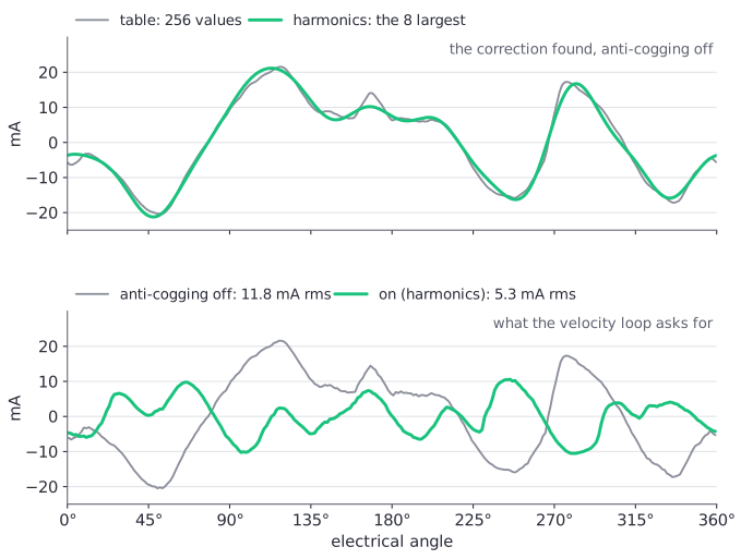
The identification switches the harmonics on. On the bench gimbal motor it found 6.8 mA rms. Parameter 38 scales the correction from 0 to 200 % for experiments; 100 % is as identified.
The angle here comes from the encoder alone, without the calibration's offset. The part of the correction that
comes from the current measurement is tied to the motor's electrical angle, though, which the offset defines.
That is one reason #Cal identifies the anti-cogging again.
The identification records the current the loops ask for, so it depends a little on the gains. After a large change of the current or velocity gains, identify it again.
The current-sense zero trim
The STEPFOC firmware can also correct the current-sense zeros from the anti-cogging's once-per-turn part (the zero trim, 43 = 4 or 5). The Spectral Micro firmware 109 skips that step until the map of its current channels is measured.
So here #Cogcal trim (43 = 4) and 43 = 5 identify like 1 and 2. The state reads 3, never 11 (done without the
trim). The combined runs and the runs after a #Cal ask for the trim too, with the same result.
Parameters 62 and 63 hold the 1st harmonic before and after a trim, in 0.1 mA. After a run that asked for the trim, both read the 1st harmonic of the set found.
The trims (parameters 59 and 60, up to ±60 counts) change only when written. They are saved with the encoder table and added to the zero the driver measures at every start-up.
Parameter 56 has no effect on the Spectral Micro. It keeps its number so that the two drivers' parameters match.
#Cal always runs both corrections, #Calonly neither.
Running them
The driver must be calibrated and without an error. Each run has a UART command and a CAN parameter:
| What | UART | CAN: Send_Parameter |
|---|---|---|
| the encoder table, used at once | #Encal |
52 = 1 |
| the encoder table, used and saved | #Encal save |
52 = 2 |
| the encoder table, then the anti-cogging, then save all | #Encal all |
52 = 3, or 43 = 3 |
| the anti-cogging, switched on | #Cogcal |
43 = 1 |
| the anti-cogging, switched on and saved | #Cogcal save |
43 = 2 |
| stop a run | #Encal stop, #Cogcal stop |
52 = 0, 43 = 0 |
#Encal stop does not stop the anti-cogging part of a combined run (#Encal all). #Cogcal stop stops a run
in either part, and so do 52 = 0 and 43 = 0 over CAN.
- Make sure the shaft is free: nothing on it and nothing it could drive.
- Send the run's command from the table, on the UART or over CAN.
- Send nothing else while the motor turns, one revolution forward and one back for each run.
- Read the result with
#Encal stateor#Cogcal state, or parameter 52 or 43 over CAN.
Check
The state reads 3, done. The motor holds the position the shaft reached. Any other state is in the table "When a run fails" under Checking them.
Both runs keep the CAN watchdog fed while they go, and end by holding the position the shaft reached. They stop at once when a host sends a command (a motion command, Idle) or an error comes up. Nothing is saved then.
While a run turns the motor a capture is not armed. During the anti-cogging run parameters 34 and 35 refuse a write: the runs use the capture's memory and the histogram.
A save from a run is the whole configuration, as #Save writes it. After a change of the motor, the magnet or
its position, run the encoder table and the anti-cogging again, in that order, or calibrate again.
Two guards keep a correction from running on the wrong data:
- parameter 37 refuses 1 or 2 while no set is stored for that form;
- an encoder table measured on its own (52 = 1 or 2) switches an anti-cogging set from before off, because that set was found on the uncorrected encoder. The anti-cogging state then reads 10 until it is identified again.
Checking them
#Info ends with what is in force:
In force:
  encoder table: on, error 0.61 deg p-p
  anti-cogging: on (harmonics), saved
  current-sense zero trim: 0 / 0 counts
  delay compensation: 234 us
  speed estimate: direct PLL, 100 Hz
  input filter: off; integral deadband: off
The example shows the defaults, with an example encoder error. While a run goes, a line
running: encoder table or running: anti-cogging identification follows.
#Encal state and #Cogcal state print one run's state without starting it. After a finished identification
(state 3) it also lists the harmonics. Parameter 43 gives the same state over CAN.
Over CAN the same is in the parameters (the parameter table):
| Parameter | What it tells | On the bench gimbal motor |
|---|---|---|
| 52 | the encoder table's state: 3 done, 4 aborted, 5 error or not calibrated, 6 the rotor did not follow, 7 rejected | 3 |
| 54 | the table's error peak to peak, 0.01° of the shaft | 50 (0.50°) |
| 55 | the amplitude of its once-per-turn part, 0.01° of the shaft | |
| 57 | how far the last table moved the electrical offset, 0.1° electrical | |
| 43 | the anti-cogging state: 3 done, 6 the shaft did not turn | 3 |
| 45 | the cogging current found, 0.1 mA rms | 68 (6.8 mA) |
| 79 | the bits of what is in force, see What is in force |
Send_Buffer_Read reads the corrections themselves: kind 4 the encoder table (128 values in 1/16 count), kind 2 the harmonics, kind 3 the anti-cogging table (Respond_Buffer_Data).
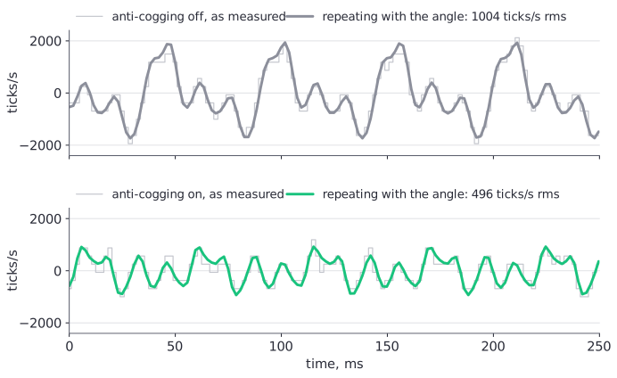
A capture of the speed while the motor turns slowly, with the anti-cogging off and on (Status and diagnostics), shows whether it helps on your motor.
On the STEPFOC's bench NEMA 17 the speed ripple that repeats with the angle was 1.2 to 2 times smaller with the anti-cogging on, at 1500 to 6000 ticks/s. The Spectral Micro has not been measured this way yet.
When a run fails:
| State | Cause | What to do |
|---|---|---|
| 52 = 6, 43 = 6 | the rotor did not follow: the shaft is blocked, or the current is too low to turn it | free the shaft; for the encoder table raise the current limit (it uses 80 % of it) |
| 52 = 5, 43 = 5 | the driver was in error or is not calibrated | #Error, clear it, calibrate |
| 52 = 4, 43 = 4 | a command came first | run it again and send nothing meanwhile |
| 52 = 7 | the table is implausible | check the magnet: glued, centred, at the right distance (The encoder magnet), then calibrate |
| 43 = 8 | the encoder table of a combined run failed | parameter 52 says why |
When a run fails after a #Cal, the calibration itself is still good: save it with #Save.
Switching them off
| UART | CAN: Send_Parameter | |
|---|---|---|
| the encoder table off / on | #Encal off, #Encal on |
53 = 0, 53 = 1 |
| the anti-cogging off, harmonics, table | #Par 37,0, #Par 37,1, #Par 37,2 |
37 = 0, 1, 2 |
| how much of the anti-cogging | #Par 38, and the percentage |
38 = 0 to 200 (%) |
#Save keeps the switches with the corrections. #Default clears both corrections and the trims.
STEPFOC
The STEPFOC firmware 109 has the same encoder table and anti-cogging, and the current-sense zero trim as well. Its manual says more.
Comments
Found a mistake on this page? Edit it on GitHub · Report it · Get help · This page as Markdown · llms.txt · The whole manual as PDF