1. Fit the motor
The driver goes on the back of the motor, over a magnet on the motor's rear shaft.
1. Fit the magnet
- Press the magnet onto the rear shaft, centred.
- Glue it, so that it cannot turn on the shaft.
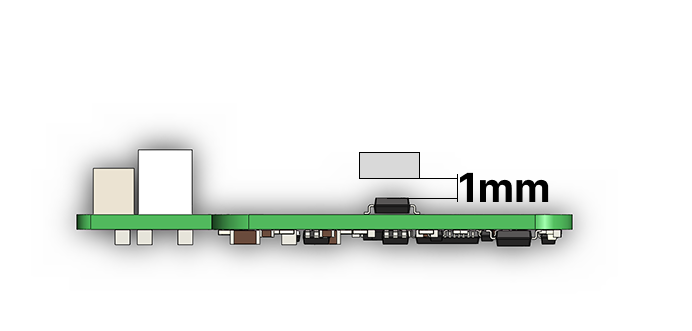
The magnet must end up about 1 mm above the encoder chip in the middle of the board.
A magnet that slips is the usual cause of a calibration that "succeeds" and a motor that then runs badly.
Check
The magnet sits centred on the shaft, and once the glue has set it does not move when you push it with a finger. If it does: The encoder magnet.
More: The encoder magnet.
2. Mount the board
- Remove the motor's four rear screws.
- Put the spacer on.
- Put the board on the spacer, with the encoder chip towards the magnet.
- Put the longer screws in.
- Check the gap between the magnet and the encoder chip: 1 mm, not touching.
Check
The board sits parallel to the back of the motor, with about 1 mm between the magnet and the encoder chip, and the shaft turns by hand without the magnet touching the chip. If not: Mounting on the motor.
More: Mounting on the motor.
3. Wire the motor
- Find the two coils with a multimeter. The two wires of a coil show a few ohms; wires of different coils show nothing.
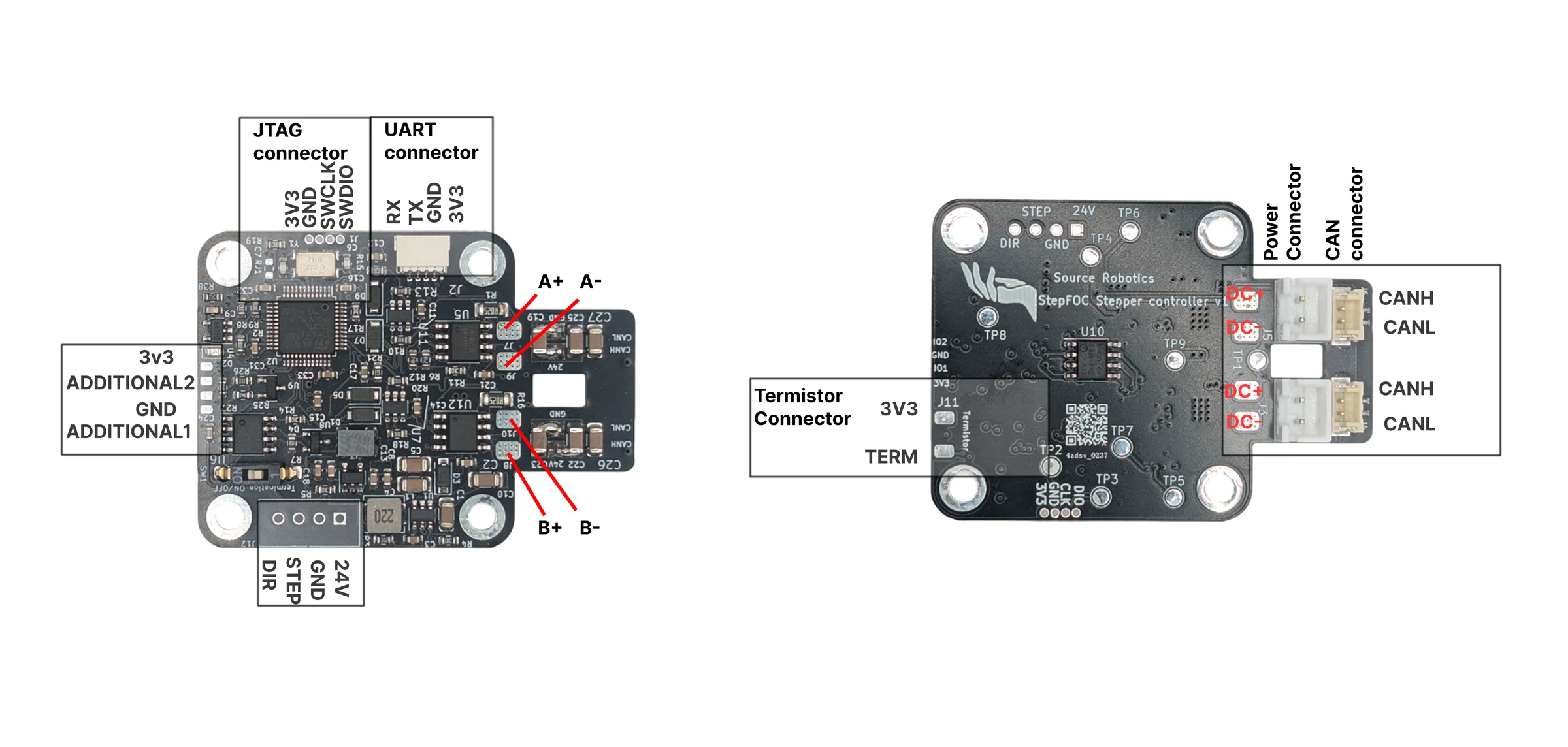
- Solder one coil to A+ and A−.
- Solder the other coil to B+ and B−.
Which coil is which, and which way round, does not matter: calibration detects it.
Check
With the driver unpowered, a multimeter shows the coil's resistance, a few ohms, between A+ and A− and between B+ and B−, and no strand bridges two pads. If not: Wiring the stepper.
More: Wiring the stepper.
Comments
Found a mistake on this page? Edit it on GitHub · Report it · Get help · This page as Markdown · llms.txt · The whole manual as PDF