Connecting
The robot needs three connections to run. They are on the back of the base.
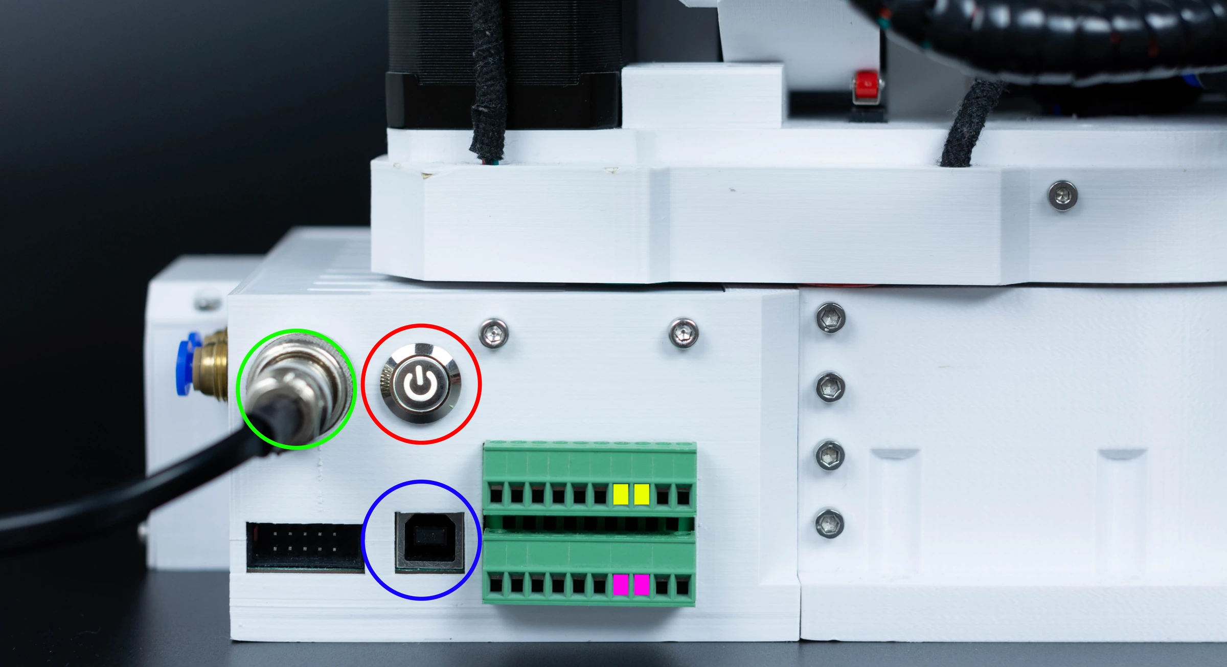
| Connection | Connector | Notes |
|---|---|---|
| 24 V power | GX16 2-pin | From the 24 V 5 A supply. Mind the polarity when you wire your own cable: the board has no reverse-polarity protection |
| USB | USB type B | To the PC. USB does not power the board |
| E-stop | Two screw terminals | A normally closed contact between them. Open means stop |
Plug the power supply into the mains through a switch within your reach, a switched socket strip for example: it is the stop that still works when the PC software has frozen (Emergency stop).
The E-stop
The E-stop must be a normally closed contact: pressing it, unplugging it or cutting its wire opens the circuit, and all of these stop the robot, which is what you want. A normally open button does not work. The control board has two E-stop connectors on the same input, so a second button can be wired in series.
The kit's button comes with a printed housing and a PG7 cable gland. Emergency stop says what happens when it is pressed, and the Control Board Manual has the wiring diagram.
The gripper
An electric gripper (SSG-48, MSG) plugs into the M8 connector at the forearm, which carries 24 V and CAN: Electric grippers. Pneumatic tubes from the valve go to the two push-in fittings at the base: Pneumatics.
Inputs and outputs
The two inputs, two outputs and their supply terminals are on the side of the control board, reachable through the base: Inputs and outputs.
Nothing else on the programming port
The 2×5-pin programming header next to the USB port is for the ST-Link programming adapter only. An ST-Link connected with plain jumper wires without the adapter has destroyed boards. See Firmware.
Comments
Found a mistake on this page? Edit it on GitHub · Report it · Get help · This page as Markdown · llms.txt · The whole manual as PDF